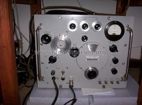
UHF Signal Generator 614A
Hewlett-Packard, (HP); Palo Alto, CA
- Pays
- Etats-Unis
- Fabricant / Marque
- Hewlett-Packard, (HP); Palo Alto, CA
- Année
- 1949 ?
- Catégorie
- Appareils de mesure et de dépannage (matériel de labo)
- Radiomuseum.org ID
- 157618
From August 1949 Communications magazine.
- Gammes d'ondes
- Bandes en notes
- Tension / type courant
- Alimentation Courant Alternatif (CA) / 115/230 Volt
- Matière
- Boitier métallique
- De Radiomuseum.org
- Modèle: UHF Signal Generator 614A - Hewlett-Packard, HP; Palo Alto
- Forme
- Modèle de table générique
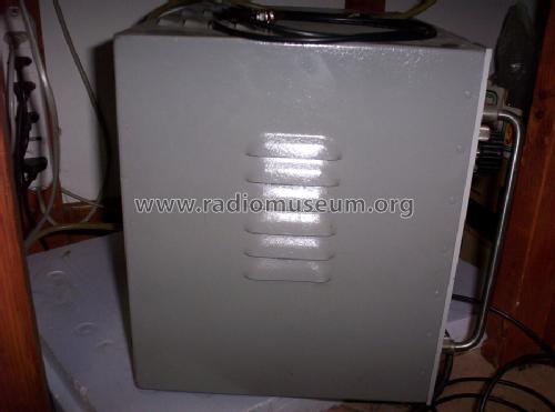
- Dimensions (LHP)
- 17 x 13.25 x 13.25 inch / 432 x 337 x 337 mm
- Remarques
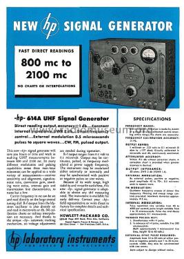
- 800 to 2100MHz, 1% accuracy. CW, square wave, pulse or FM. This new UHF Signal Generator is similar in design to the hp-616A generator, but offers such additional advantages as faster rise time of pulsed output, more constant internal impedance and higher output accuracy.
Like the 616A, the new 614A can save hours of time and work in making UHF measurements. It offers direct reading output and accuracy of ± 1 db; constant internal impedance with a standing wave ratio of 3 db; external modulation of half-microsecond pulses to square waves; a choice of CW, FM or pulsed output, and many other time-saving conveniences.
For example, carrier frequency in mc can be set and read directly on the large central tuning dial. Rf output from the klystron oscillator is also directly set and read, in microvolts or db. No calibration charts or tedious interpolations are necessary; and no voltage adjustments are required during operation. Output may be continuous, pulsed, or frequency modulated at power supply frequency. The instrument can be modulated internally or externally; and may be synchronized with positive or negative pulses or sine waves.
With this instrument you can quickly, easily and accurately measure receiver sensitivity and alignment, signal-to-noise ratio, conversion gain, standing wave ratios, antenna gain, and transmission line characteristics—to name but a few readings essential to UHF work.
SPECIFICATIONS
Frequency Range: 800-2,100 mc directly calibrated. Accurate within ±1%.
Output Range: 1 milliwatt or .223 v to 0.1 µv. (0 dbm to —127 dbm) Directly calibrated in Liv and db; continuously monitored.
Output Impedance: 50 ohms. SWR 3 db (VSWR 1.4).
External Modulation: By external pulses, pos. or neg. peak amplitude 40 to 70 v., 0.5 microseconds to square wave.
FM Modulation: Oscillator frequency sweeps at power line frequency. Phasing and sweep range controls provided. Max. deviation approx. ±5 mc. Internal Modulation: Pulse repetition rate variable from 40 to 4,000 per second; pulse length variable from 1 to 10 µsec. Pulse rise and decay approx. 0.1 µsec.
Trigger Pulses Out: (1) Simultaneous with rf pulse. (2) In advance of rf pulse, variable 3 to 300 µsec. (Both approx. I µsec. rise time, height 10 to 40 v.) External SYNC Pulse Needed: Amplitude from 10 to 50 v. of either pos. or neg. polarity; and 1 to 20 µsec width. May also be synchronized with sine waves.
- Poids net
- 115 lb 0 oz (115 lb) / 52.210 kg
- Prix de mise sur le marché
- 1,950.00 $
- Source
- -- Original prospect or advert
- Schémathèque (1)
- Electronics, April 1955
- Auteur
- Modèle crée par Emilio Ciardiello. Voir les propositions de modification pour les contributeurs supplémentaires.
- D'autres Modèles
-
Vous pourrez trouver sous ce lien 399 modèles d'appareils, 367 avec des images et 139 avec des schémas.
Tous les appareils de Hewlett-Packard, (HP); Palo Alto, CA
Collections
Le modèle UHF Signal Generator fait partie des collections des membres suivants.