Boonton Q-Meter 160-A
Hewlett-Packard, (HP); Palo Alto, CA
- Land
- USA
- Hersteller / Marke
- Hewlett-Packard, (HP); Palo Alto, CA
- Jahr
- 1959 ??

- Kategorie
- Service- oder Labor-Ausrüstung
- Radiomuseum.org ID
- 82822


Klicken Sie auf den Schaltplanausschnitt, um diesen kostenlos als Dokument anzufordern.
- Anzahl Röhren
- 3
- Röhren
- Hauptprinzip
- Spezielle Schaltung? Bitte bei Bemerkung nachtragen.
- Wellenbereiche
- Wellen in den Bemerkungen.
- Betriebsart / Volt
- Wechselstromspeisung / 115 Volt
- Lautsprecher
- - - Kein Ausgang für Schallwiedergabe.
- Material
- Metallausführung
- von Radiomuseum.org
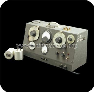
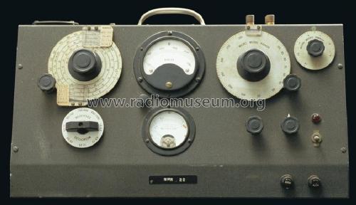
- Modell: Boonton Q-Meter 160-A - Hewlett-Packard, HP; Palo Alto
- Form
- Tischgerät, Schräg-Pult-Form.
- Bemerkung
-
The Boonton Q-Meter Type 160-A covers 50 kHz to 75 MHz with the internal oscillator, and 1 kHz to 50 kHz with an external oscillator. With the internal multipliers Qs from 0 to 625 can be measured, and special measurement techniques can measure capacitor Qs as high as 10,000. The basic accuracy is ±5%.
The Boonto Q-Meter has been designed in 1934 and the market introduction was May 1935. According to HP-Information, the instrument was still in production when HP aquired Boonton in 1959, but we believe it was the follower, the 260-A. This HP page puts the Q-Meter Type 160-A to the year 1946 which is definitively wrong. See also Boonton.
Boonton: New Jersey-based Boonton Radio Corporation was founded in 1934 by W. D. Loughlin and several associates and was a manufacturer of electronic test instruments. The new firm concentrated its engineering skill on creating new measuring equipment for the still-young radio industry.
HP acquired Boonton in 1959 as a wholly-owned subsidiary. By then the firm had 150 employees and was a pioneer maker of precision instruments for measuring electrical circuit quality and checking aircraft guidance systems. In a year of phenomenal growth for HP (the company acquired three other firms in 1959), Boonton added to the HP family an old, well-established company with an excellent reputation in a field closely related to many HP products.
The Q-Meter was Boonton's oldest instrument-the first one having been introduced by the company in 1935. It measures the quality factor of coils and other components used in electronic devices and had broad applications in the testing of components and systems.
- Autor
- Modellseite von Ernst Erb angelegt. Siehe bei "Änderungsvorschlag" für weitere Mitarbeit.
- Weitere Modelle
-
Hier finden Sie 399 Modelle, davon 367 mit Bildern und 139 mit Schaltbildern.
Alle gelisteten Radios usw. von Hewlett-Packard, (HP); Palo Alto, CA
Forumsbeiträge zum Modell: Hewlett-Packard, HP;: Boonton Q-Meter 160-A
Threads: 2 | Posts: 3
I see two version of the same equipment Boonton 160A, one listed under Boonton and the other under Hp.I presume the latter should merge in the former.
Antonio Marra, 18.Sep.16
Dieses Gerät haben wir im Radiolabor Horny auch verwendet.
Zubehör waren einige Induktivitäten mit genau bekanntem Q und bei welcher Frequenz es gilt. Z.B. 203 bei 1 MHz.
Ich habe mich damals über die Schaltung informiert, welches Messprinzip dahintersteckt.
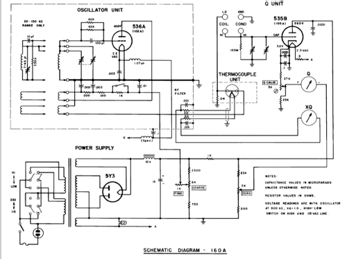
Links in der Schaltung ist ein gewönlicher Oszillator, den man mittels GROB und FINE auf eine Marke auf dem kleinen Instrument einstellen musste. Gemessen wurde das mit dem Thermocouple Unit, in dem sich auch der Einkoppelwiderstand von nur 0,04 Ohm für dem Messschwingkreis mit der unbekannten Spule und dem eingebauten Drehkondensator hoher Güte befindet. Begrenzt wurde die Güte mit dem 100 MOhm Widerstand parallel zum Schwingkreis und dem Einspeisewiderstand von 0,04 Ohm. Natürlich musste der Aufbau der Röhrenumgebung äußerst hochohmig und feuchteabweisend sein.
Vor der Messung bei der gewünschten Frequenz, musste noch auf dem Q-Anzeigeinstrument, das sich in einer Brücke, siehe Schaltung, befand, dieses auf "Null" gestellt werden. Danach stimmte man den Schwingkreis ab und konnte unmittelbar den Q-Faktor ablesen.
Die Gleichrichterschaltung ist ein sogenannter Kathodengleichrichter, der ein phantastischer Spitzenwertgleichrichter ist. Für Detektoren eignet sich das vorzüglich, aber es ist dann kein passiver Detektor mehr, nur nebenbei. Heute mit FET.
Wenn man die Schaltung aus heutiger Sicht betrachtet, fällt auf, wie viele "Nebentätigkeiten" erforderlich waren, ehe man ein Ergebnis hatte. Heutzutage wählt man die Messfrequenz und liest das Ergebnis ab.
Rudolf Drabek, 08.Apr.13