Mass Memory Recorder MMR-1
International Video Corporation; Sunnyvale (CA)
- Country
- United States of America (USA)
- Manufacturer / Brand
- International Video Corporation; Sunnyvale (CA)
- Year
- 1972 ?
- Category
- Signal Processing and Computing
- Radiomuseum.org ID
- 305659
-
- alternative name: IVC


Manufacturer's documentation.
Manufacturer's documentation.

Manufacturer's documentation.

Manufacturer's documentation.
Click on the schematic thumbnail to request the schematic as a free document.
- Wave bands
- - without
- Details
- Video-Taperecorder/-Player
- Power type and voltage
- Alternating Current supply (AC) / 110-120 Volt
- Loudspeaker
- - - No sound reproduction output.
- Material
- Metal case
- from Radiomuseum.org
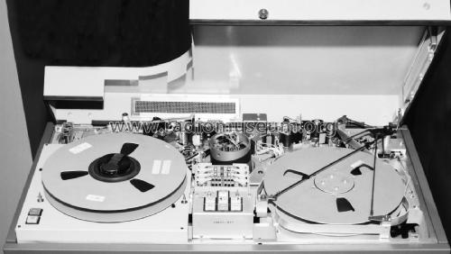
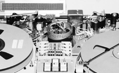
- Model: Mass Memory Recorder MMR-1 - International Video
- Shape
- Console with Push Buttons.
- Dimensions (WHD)
- 35 x 37 x 19 inch / 889 x 940 x 483 mm
- Notes
-
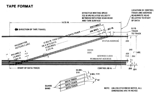
The IVC MMR-1 (initially named IVC-1000) was a digital mass memory recorder that used 1" helical scan video recording technology to achieve a much higher data recording density than is possible with conventional multitrack fixed head tape recorders. The rotating scanner records about 100 tracks across the tape at a linear density of 11,000 bits/in, resulting in an information density of over 1 million bits per square inch. The recording media are standard 3M magnetic video tapes, and each 12.5" reel of 7000 ft of tape has a capacity of 90 Gbits without redundancy.
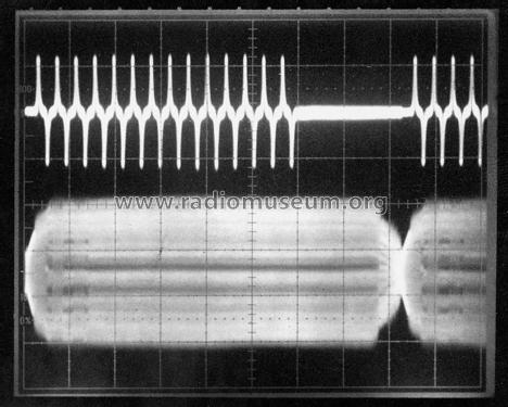
The scanner has rotating erase, read/write and write verify heads that are coupled to the fixed part of the assembly by rotary transformers. The signal from the write verify head only indicates the general quality of the high density data recording. The scanline length is about 12" and the data are recorded in Miller code at 8.1 MHz. The scanner operating speed is 3600 rpm, and the heads retract automatically at the idling speed of 2400 rpm.
In addition to the high density diagonal scanlines, control, permanent address and clock tracks are recorded longitudinally near the lower edge of the tape, and a status track is recorded near the upper edge. The address and status tracks can be read in either direction at search speeds up to 400 ips. The longitudinal tracks have fixed preview, read/write and read-after-write heads. The separation between each status record and the scanline with which it is associated is chosen such that the status is between the preview and read/write heads when the corresponding high-density data are scanned. Hence it is possible to make a high-density read or write decision on the basis of the status read at the preview head, and to update the status information at the read/write head by the data read from the scanline. Because of the frequency and recording density differences, the scanner can record or erase over the address tracks without corrupting address information.
Tape tension information for the reel servos is determined by photo-optical sensing of the position of the tension arms, which are unusually short. Two sense blocks use LEDs and phototransistors to detect the leader marker, EOT and BOT markers and broken tape. Each of the two idler tachometers employs a glass encoder wheel with a 500-line photo-emulsive coating, a small lined glass reticule and a dual photosensitive IC pickup producing two outputs 90 degrees apart.
Tape write speed:
6.91 ips linear (723 ips scan head-to-tape speed).
Tape read speed:
Image data 6.91 ips.
Address data (search mode) up to 400 ips bidirectional.Image data (rotating head):
Input/output data rate 8.1 Mbits/s.
Tape packing density 1 x 106 bits/in2.
Recording density 11,000 bits/in.
Data scanline length 120,000 bits maximum.
Average error rate less than 1 in 106 bits (uncorrected).
Input/output data NRZ plus clock.Address data:
Address input rate 1800 bits/s.
Address output rate 1800 bits/s at 6.91 ips, 104 kbits/s at 400 ips.
Amplitude is compensated for variation with search speed.
Permanent address and updateable status words 22 bits plus 2 checkbits.
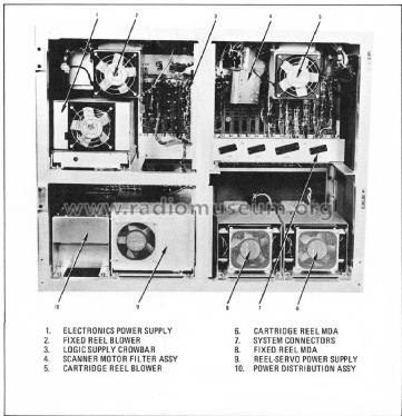
Recording density 260 bits/in.The MMR-1 was a mass storage device rather than a system, and it didn't include a controller, computer, buffer memory, staging discs or software. It was specified for operation from a 115v ±5% 60 Hz AC supply, but could be operated from 230v 50 Hz via a 2.3 kVA autotransformer. (The main timing frequency that synchronises the scanner and capstan remained 60 Hz, as it was independent of the mains supply). Six blowers at the rear of the machine cooled the electronics and reel servo power supplies, the reel motors and the motor drive amplifiers.
- Net weight (2.2 lb = 1 kg)
- 400 lb (400 lb 0 oz) / 181.6 kg
- Author
- Model page created by Bruce Taylor. See "Data change" for further contributors.
- Other Models
-
Here you find 7 models, 5 with images and 1 with schematics for wireless sets etc. In French: TSF for Télégraphie sans fil.
All listed radios etc. from International Video Corporation; Sunnyvale (CA)
Collections
The model Mass Memory Recorder is part of the collections of the following members.