Oscilloscope AN/USM-50
MILITARY U.S. (different makers for same model)
- Pays
- Etats-Unis
- Fabricant / Marque
- MILITARY U.S. (different makers for same model)
- Année
- 1957 ??
- Catégorie
- Appareils de mesure et de dépannage (matériel de labo)
- Radiomuseum.org ID
- 336409


Cliquez sur la vignette du schéma pour le demander en tant que document gratuit.
- No. de tubes
- 43
- Lampes / Tubes
- 6AH6 5915 or 6AS6 5726 or 6AL5W 6AU6 6CB6 12AT7WA 12AU7 12B4A 12BH7A 12BY7A 6080 5642 5651 3ADP-
- Gammes d'ondes
- - sans
- Tension / type courant
- Alimentation Courant Alternatif (CA) / 50-60 Hz: 105-125 Volt
- Haut-parleur
- - - Pas de sortie basse fréquence
- Matière
- Boitier métallique
- De Radiomuseum.org
- Modèle: Oscilloscope AN/USM-50 - MILITARY U.S. different makers
- Forme
- Modèle de table générique
- Dimensions (LHP)
- 490 x 390 x 380 mm / 19.3 x 15.4 x 15 inch
- Remarques
-
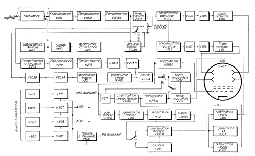
This Oscilloscope has the following characteristics;
Sinusoidal response for the vertical amplifier: from 3 to 15 MHz.
Vertical amplifier rise time: 22 nsec.
Vertical amplifier delay: 250 nsec.
Vertical amplifier droop: lower than 5% on pulses of 15,000 µsec.
Vertical sensitivity: 10 mV/cm.
Upward deflection by positive polarity.
Vertical amplifier input impedance: 1 MΩ in parallel with 40 pF.
Response for the horizontal amplifier: between 10 and 750 kHz.
Variable sensitivity: between 1.2 and 80 V peak-to-peak/cm of horizontal deflection.
Horizontal amplifier input impedance: 1 MΩ in parallel with 30 pF.
Rise time of the horizontal route: 20 nsec.
Variable time axis generator: continuously variable from 0.2 to 37,000 µsec/inch of horizontal deflection (0.08 to 10,800 µsec/cm).
Mode of operation of the time axis: Auto or Triggered.
Sweep delay: option to expand x 10 every tenth of the horizontal trace, up to a speed of the time axis of about 2 µsec/cm.
1 kHz rectangular wave calibrator with variable amplitude from 0.01 to 0.1 V peak-to-peak for internal use and fixed output of 30 V peak-to-peak.
Trigger generator: continuously variable from 10 to 10,000 pulses/sec in three ranges of one decade. Width of a 1.2 µsec pulse, with a rise time of 150 nsec.
Positive and negative output of trigger pulses for external use.
Mark generator with modulation of beam intensity with a cadence of 0.2 - 1 - 5 - 20 - 100 - 500 - 2,000 µsec.Supplied to the US Army from 1957 until about 1970.
This information has been translated from the text on CQ Elettronica, written by Eng. Marcello Fabio Francardi, author of the article.
Some tubes are listed once.
- Poids net
- 13 kg / 28 lb 10.1 oz (28.634 lb)
- Littérature
- CQ Elettronica, CD editor, number 1, January 1977
- Auteur
- Modèle crée par Pier Antonio Aluffi. Voir les propositions de modification pour les contributeurs supplémentaires.
- D'autres Modèles
-
Vous pourrez trouver sous ce lien 408 modèles d'appareils, 360 avec des images et 215 avec des schémas.
Tous les appareils de MILITARY U.S. (different makers for same model)
Collections
Le modèle Oscilloscope fait partie des collections des membres suivants.