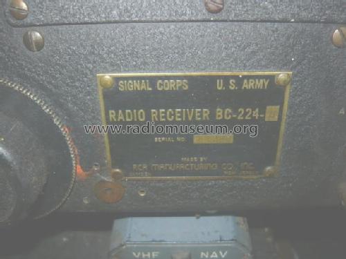
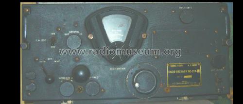
Radio Receiver BC-224-(*)
MILITARY U.S. (different makers for same model)
- Country
- United States of America (USA)
- Manufacturer / Brand
- MILITARY U.S. (different makers for same model)
- Year
- 1936–1947 ?
- Category
- Military Receiver
- Radiomuseum.org ID
- 259937

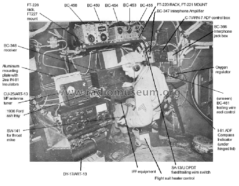
B-29 Radio assembly.
Click on the schematic thumbnail to request the schematic as a free document.
- Number of Tubes
- 9
- Valves / Tubes
- 6B8 or VT-93 6C5 or VT-65 6F7 or VT-70 6J7 or VT-91 6K7 or VT-86 6K7 or VT-86 6K7 or VT-86 41 or VT-48 991
- Main principle
- Superheterodyne (common)
- Wave bands
- Broadcast plus more than 2 Short Wave bands.
- Power type and voltage
- Batteries / addl. power jack / 14 Volt
- Loudspeaker
- - For headphones or amp.
- Material
- Metal case
- from Radiomuseum.org
- Model: Radio Receiver BC-224- - MILITARY U.S. different makers
- Shape
- Boatanchor (heavy military or commercial set >20 kg).
- Notes
-
Radio Receiver BC-224-(*) (Generic model - search also for model variants with different suffixes): Aircraft receiver covering medium - and shortwaves in six bands, modes AM (A3) and CW (A1, with BFO) powered by 14 V DC from aircraft on-board power system.
The first BC-224-A receiver was constructed by RCA
Based on U.S.Air Force receiver experience with this receiver, an improved model was produced with suffixes BC-224-B, BC-224-C, BC-224-D. RCA then started to produce a 28V DC version of this receiver which became the BC-348-B, the first receiver in the very successful series of BC-348 receivers.
Then the U.S.Signal Corps had the demand to incorporate the 200 - 500 KHz longwave band (used in the U.S. for beacons, not for communications) in the receiver and to compress the 1,5 - 18 MHz tuning range in the remaining five bands, this receiver became the BC-224-E, followed by receivers with higher suffix numbers. In those, frequency coverage was similar, in the BC-224-F (and -K), the output tube was changed to the 6K6. The 28V DC equivalent of the receivers covering the longwave / beacon band was the BC-348-E and higher suffix letters.
The receivers saw use in bomber aircraft from World War II until Corean War, it is reported that one of these receiver was onboard the "Enola Gay" at it's 6. Aug. 1945 mission.
Please do upload your model images to the best matching model variant page. - Bilder bitte auf die am besten passende Varianten - Modellseite laden.
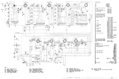
The uploaded schematic, from an article of the lamented I1BIN Umberto Bianchi on CQ Elettronica, Italian magazine, indicates power supply via Dynamotor, separated from the appliance and therefore for use in the absence of another power supply.
- Net weight (2.2 lb = 1 kg)
- 40 lb (40 lb 0 oz) / 18.160 kg
- Mentioned in
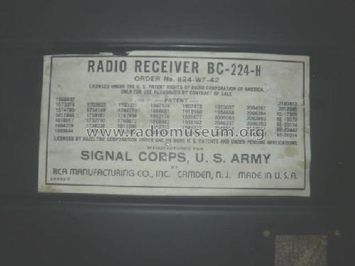
- -- Schematic (From "CQ Elettronica", Italy, CD editor, number 12 December 1970)
- Author
- Model page created by Michael Gnaedig-Fischer. See "Data change" for further contributors.
- Other Models
-
Here you find 408 models, 360 with images and 215 with schematics for wireless sets etc. In French: TSF for Télégraphie sans fil.
All listed radios etc. from MILITARY U.S. (different makers for same model)
Collections
The model Radio Receiver is part of the collections of the following members.
Forum contributions about this model: MILITARY U.S.: Radio Receiver BC-224-
Threads: 1 | Posts: 1
Hello,
as far as I see it (and from knowing the sibling 28 V DC set BC-348), the set has indeed a dynamotor power supply to generate the high (plate) voltages. The complete dynamotor power assembly is located inside the cabinet, it has the designation BD-94-A.
It is powered via internal connectors from the 14 V DC airplane power system.
So from the schematic, it might look like an external power supply, but it is located inside the cabinet and thus part of the receiver.
Radionerds.com have the complete TO 08-10-24 manual for download.
Kind regards
Martin
Martin Bösch, 18.Sep.22