52L2 Ch= HS-327
Motorola Inc. (ex Galvin Mfg.Co. Chicago); Schaumburg (IL)
- Land
- USA
- Hersteller / Marke
- Motorola Inc. (ex Galvin Mfg.Co. Chicago); Schaumburg (IL)
- Jahr
- 1953/1952 ?
- Kategorie
- Rundfunkempfänger (Radio - oder Tuner nach WW2)
- Radiomuseum.org ID
- 48880


Klicken Sie auf den Schaltplanausschnitt, um diesen kostenlos als Dokument anzufordern.
- Anzahl Röhren
- 4
- Anzahl Transistoren
- Halbleiter
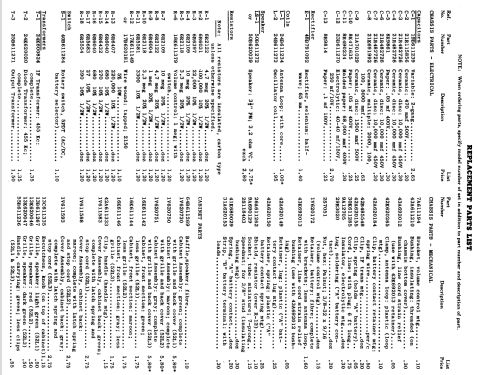
- Selenium-Rectifier
- Hauptprinzip
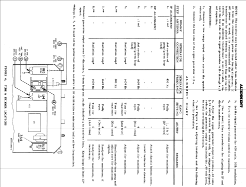
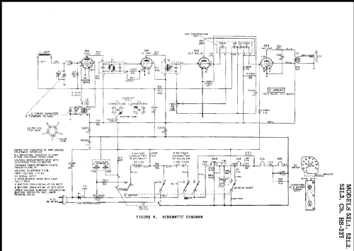
- Superhet allgemein; ZF/IF 455 kHz; 2 NF-Stufe(n)
- Anzahl Kreise
- 6 Kreis(e) AM
- Wellenbereiche
- Mittelwelle, keine anderen.
- Betriebsart / Volt
- Netz- / Batteriespeisung / AC/DC 117V =110-120/ 67.5 & 3 Volt
- Lautsprecher
- Dynamischer LS, keine Erregerspule (permanentdynamisch) / Ø 3.5 inch = 8.9 cm
- Material
- Plastikgehäuse (nicht Bakelit), Thermoplast
- von Radiomuseum.org
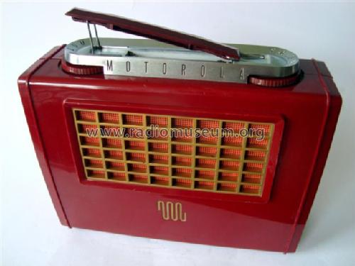
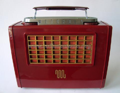
- Modell: 52L2 Ch= HS-327 - Motorola Inc. ex Galvin Mfg.Co
- Form
- Reisegerät > 20 cm (netzunabhängig betreibbar)
- Bemerkung
-
There are six models in this series. The later "A" models added a "B" Battery Saver slide switch, located in the upper right corner of the speaker grill. The two slide switch positions are: left (DISTANCE-HI), and right (LOCAL-LO). The DISTANCE-HI position increased the "B" battery drain and improved reception for long distance broadcasts. The original model "B" battery drain was fixed at the later "A" model DISTANCE-HI drain level.
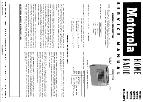
Model Chassis Color Battery Saver Switch 52L1 HS-327 Green NO 52L2 HS-327 Maroon NO 52L3 HS-327 Gray NO 52L1A HS-357 Green YES 52L2A HS-357 Maroon YES 52L3A HS-357 Gray YES Motorola model 52L2 is a three power portable AM superheterodyne receiver.
- Datenherkunft extern
- Ernst Erb
- Schaltungsnachweis
- Rider's Perpetual, Volume 23 (last), covering up to 1954
- Literaturnachweis
- Guide to Old Radios
- Literatur/Schema (1)
- Photofact Folder, Howard W. SAMS (Set 190, folder 11, dated 1-53)
- Literatur/Schema (3)
- Motorola Folder No. 3301 for 1952.
- Weitere Modelle
-
Hier finden Sie 4653 Modelle, davon 2980 mit Bildern und 4153 mit Schaltbildern.
Alle gelisteten Radios usw. von Motorola Inc. (ex Galvin Mfg.Co. Chicago); Schaumburg (IL)