A17W Ch= HS-922
Motorola Inc. (ex Galvin Mfg.Co. Chicago); Schaumburg (IL)
- Produttore / Marca
- Motorola Inc. (ex Galvin Mfg.Co. Chicago); Schaumburg (IL)
- Anno
- 1961

- Categoria
- Radio (o sintonizzatore del dopoguerra WW2)
- Radiomuseum.org ID
- 254180


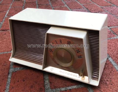
Motorola A17W
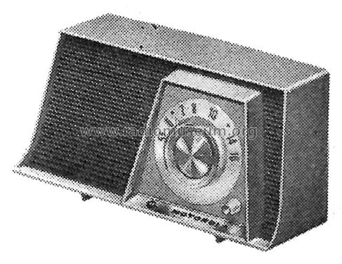
Picture from Motorola Datasheet

RECONSTRUCTED LABEL
Clicca sulla miniatura dello schema per richiederlo come documento gratuito.
- Numero di tubi
- 5
- Principio generale
- Supereterodina (in generale); ZF/IF 455 kHz; 2 Stadi BF
- N. di circuiti accordati
- 6 Circuiti Mod. Amp. (AM)
- Gamme d'onda
- Solo onde medie (OM).
- Tensioni di funzionamento
- Alimentazione universale (doppia: CC/CA) / Either AC: 60 cycles, 120V or DC: 120 Volt
- Altoparlante
- AP magnetodinamico (magnete permanente e bobina mobile) / Ø 5 inch = 12.7 cm
- Materiali
- Plastica (non bachelite o catalina)
- Radiomuseum.org
- Modello: A17W Ch= HS-922 - Motorola Inc. ex Galvin Mfg.Co
- Forma
- Soprammobile compatto/con bordi arrotondati/midget senza pulsantiera/tastiera.<= 35 cm (Sometimes with handle but for mains only).
- Annotazioni
-
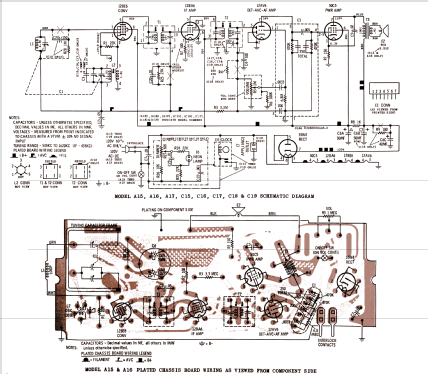
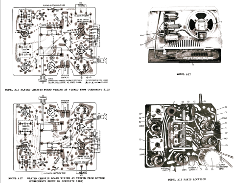
The Motorola A17W is an AC/DC operated 5 tube AM receiver. The AM tuning range is 535 - 1620kHz.
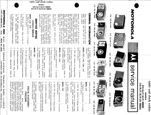
The following models use the same schematic and cabinet but have different cabinet colors:
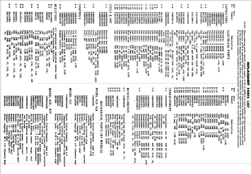
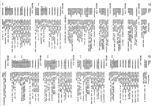
Model Cabinet Colors A17B Blue A17G Green A17W White/Brown The Motorola service manual has service information for the following models: A15, A16, A17, A18, A19 series and the C15, C16, C17, C18, C19, C20 series. The A series are radio's without clocks, while the C series are radio's with clocks.
WARNING: When servicing this radio, an isolation transformer should be used between the power line and the radio.
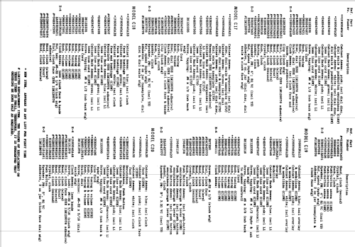
- Riferimenti schemi
- Beitman Radio Diagrams Vol. 22, 1962
- Letteratura / Schemi (1)
- - - Manufacturers Literature (Motorola Datasheet 68P60011A71 Dated 6-61)
- Letteratura / Schemi (2)
- Beitman Radio Diagrams, Vol. 22, 1962 (Page 65)
- Letteratura / Schemi (3)
- Photofact Folder, Howard W. SAMS (Set 586, folder 10 Dated 7-62)
- Autore
- Modello inviato da John Kusching. Utilizzare "Proponi modifica" per inviare ulteriori dati.
- Altri modelli
-
In questo link sono elencati 4655 modelli, di cui 2982 con immagini e 4154 con schemi.
Elenco delle radio e altri apparecchi della Motorola Inc. (ex Galvin Mfg.Co. Chicago); Schaumburg (IL)
Collezioni
Il modello A17W fa parte delle collezioni dei seguenti membri.