A18B Ch= HS-824
Motorola Inc. (ex Galvin Mfg.Co. Chicago); Schaumburg (IL)
- País
- Estados Unidos
- Fabricante / Marca
- Motorola Inc. (ex Galvin Mfg.Co. Chicago); Schaumburg (IL)
- Año
- 1961

- Categoría
- Radio - o Sintonizador pasado WW2
- Radiomuseum.org ID
- 254187


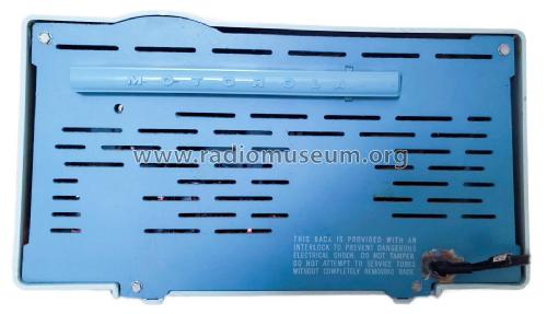
Picture from Curt Brownlow.
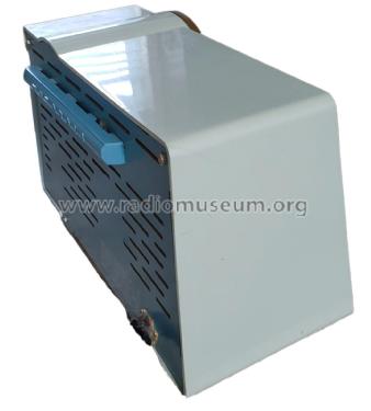
Picture from Curt Brownlow.

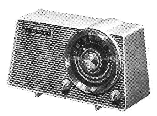
Picture from Curt Brownlow.
Picture from Curt Brownlow.
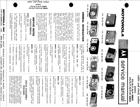
Picture from Motorola Datasheet
Haga clic en la miniatura esquemática para solicitarlo como documento gratuito.
- Numero de valvulas
- 6
- Principio principal
- Superheterodino en general; ZF/IF 455 kHz; 2 Etapas de AF
- Número de circuitos sintonía
- 6 Circuíto(s) AM
- Gama de ondas
- OM (onda media) solamente
- Tensión de funcionamiento
- Red: Aparato AC/DC. / Either AC: 60 cycles, 120V or DC: 120 Volt
- Altavoz
- Altavoz dinámico (de imán permanente) / Ø 6 inch = 15.2 cm
- Material
- Plástico moderno (Nunca bakelita o catalina)
- de Radiomuseum.org
- Modelo: A18B Ch= HS-824 - Motorola Inc. ex Galvin Mfg.Co
- Forma
- Sobremesa de tamaño mediano sin botonera <= 35 cm. (Incluso portables pero sólo con alimantación por red).
- Anotaciones
-
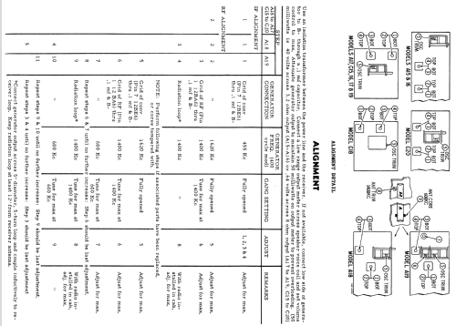
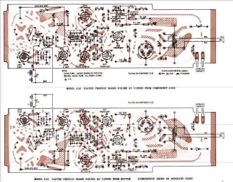
The Motorola A18B is an AC/DC operated 6 Tube AM Receiver with Selenium Rectifier and Push-Pull output stage. AM Band Tuning Range: 535 to 1620KHz.
The following models use the same schematic and cabinet but have different cabinet colors:
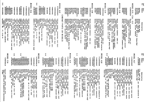
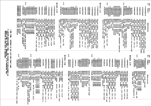
Model Cabinet Colors A18B Blue A18W White/Charcoal The Motorola service manual has service information for the following models: A15, A16, A17, A18, A19 series and the C15, C16, C17, C18, C19, C20 series. The A series are radio's without clocks, while the C series are radio's with clocks.
WARNING: When servicing this radio, an isolation transformer should be used between the power line and the radio.
- Documentación / Esquemas (1)
- - - Manufacturers Literature (Motorola Datasheet 68P60011A71 Dated 6-61)
- Autor
- Modelo creado por John Kusching. Ver en "Modificar Ficha" los participantes posteriores.
- Otros modelos
-
Donde encontrará 4655 modelos, 2982 con imágenes y 4154 con esquemas.
Ir al listado general de Motorola Inc. (ex Galvin Mfg.Co. Chicago); Schaumburg (IL)