All-Wave A36
Murphy Radio Ltd.; Welwyn Garden City
- País
- Gran Bretaña (GB)
- Fabricante / Marca
- Murphy Radio Ltd.; Welwyn Garden City
- Año
- 1937
- Categoría
- Radio - o Sintonizador pasado WW2
- Radiomuseum.org ID
- 170821


Haga clic en la miniatura esquemática para solicitarlo como documento gratuito.
- Numero de valvulas
- 8
- Principio principal
- Superheterodino doble o triple conversión; ZF/IF 1000/119 kHz
- Gama de ondas
- OM, OL y OC
- Tensión de funcionamiento
- Red: Corriente alterna (CA, Inglés = AC) / 200-260 Volt
- Altavoz
- Altavoz electrodinámico (bobina de campo)
- Potencia de salida
- 3 W (unknown quality)
- Material
- Madera
- de Radiomuseum.org
- Modelo: All-Wave A36 - Murphy Radio Ltd.; Welwyn
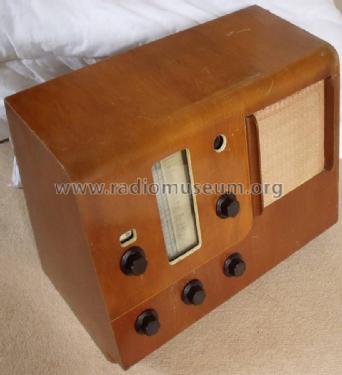
- Forma
- Sobremesa apaisado (tamaño grande).
- Ancho, altura, profundidad
- 22.15 x 16.2 x 12.6 inch / 563 x 411 x 320 mm
- Anotaciones
- Design: R.D.Russell.
Double conversion for SW.
First Murphy Radio with shortwave-reception. Extra Shortwave tuning condenser, coils and dial. SW signal fed into MW/LW section. Bandspread tuning via MW/LW coils, tuning condenser and dial.
Alphabetical tuning, Inter Station Noise Suppression.
First ACVP2 works as a reflex RF/AF amplifier, RF on shortwaves only, AF on all bands. Magic eye.
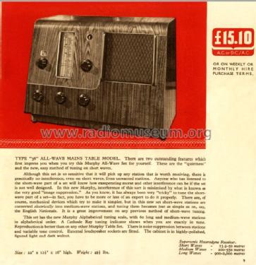
- Precio durante el primer año
- 15.00 GBP
- Procedencia de los datos
- - - Manufacturers Literature
- Autor
- Modelo creado por Sönke Gäthke. Ver en "Modificar Ficha" los participantes posteriores.
- Otros modelos
-
Donde encontrará 367 modelos, 301 con imágenes y 234 con esquemas.
Ir al listado general de Murphy Radio Ltd.; Welwyn Garden City
Colecciones
El modelo All-Wave es parte de las colecciones de los siguientes miembros.
Contribuciones en el Foro acerca de este modelo: Murphy Radio Ltd.;: All-Wave A36
Hilos: 1 | Mensajes: 1
Murphy A36
Alphabetical Tuning & Shortwave Circuits of Unusual Interest.
 In designing this receiver, the makers have set themselves the task of providing a performance on short waves which shall be comparable with that to which the majority of broadcast listeners have become accustomed to the mediumwave band. Hitherto the shortwave range has been open to criticism under three main heads: (1) Difficulty of tuning; (2) Susceptibility to image or second channel interference; (3) Inadequate reserve of gain in view of the discrepancy in field strengths between medium and shortwave signals taken as a whole.
In conventional "all-wave" receivers the first of these difficulties are met by mechanical means associated with the tuning condenser drive, but in the new Murphy set the solution is an electrical one and takes the form of a well-thought-out double frequency changing circuit which virtually broadens out tuning on shortwave stations to mediumwave standards. In working out this circuit the designers have taken items (2) and (3) in their stride and the result is a receiver which is not only of absorbing interest to the student of technical details, but a set which, in the hands of the average listener, is likely to provide far more reliable entertainment than usual on the short-wave range.
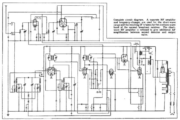 The foundation of the circuit is a four-valve superheterodyne which is a logical development of the Murphy "26,” "30" and "34" series. It has an input band-pass filter working on medium and long waves leading to a triode-pentode frequency changer, pentode IF amplifier, double diode second detector, and pentode output valve. The short waves are handled by a separate section consisting of a signal frequency amplifier and triode-hexode frequency changer. This unit has its own three-gang tuning condenser and signals are converted to an intermediate frequency falling in the medium wave band of the main receiver. Thus, the whole of the gain and selectivity of the broadcast receiver is available to supplement the already considerable signal with which it is fed from the shortwave section.
Now comes the most interesting feature of the design. Instead of keeping the intermediate frequency fixed and varying the shortwave tuning circuits by some form of "vernier" drive, the shortwave tuning condenser is fixed by locating notches at predetermined points, actually, the midpoints of the recognised shortwave broadcast bands, and the final tuning is carried out by the main tuning dial of the set. As the majority of the shortwave broadcast bands are less than 1 megacycle in width the shortwave stations in each band are spread out over the medium wave dial and tuned with the same ease as mediumwave stations. The additional valves in the shortwave section bring the shortwave programs up to the volume level of mediumwave stations and the additional pre-selection coupled with the high intermediate frequency entirely solves the problem of image or second channel interference.
Theoretically, there is one snag. Signals at the extreme ends of any given band to which the shortwave tuning condensers have been temporarily fixed by the locating notch will be off-tune with respect to the peak of the resonance curve of the shortwave circuits and a reduction of input is to be expected. In practice any loss of signal strength or deterioration of image rejection from this cause is negligible. Sufficient overall gain has been provided to give full volume from any worthwhile signals occurring at the extreme edges of the recognised shortwave broadcast bands, and any relative increase which may accrue from a station being near to the peak of the input resonance curve will be taken care of by AVC.
 The circuit is as interesting in detail as it is in the general specification. For instance, additional amplification is gleaned by reflexing the shortwave RF amplifier and pressing it into service also as an intermediate stage of AF amplification between the signal rectifying diode and the output valve.
The method of noise suppression is somewhat complicated, but the general principle of the circuit may be stated briefly as follows.
A paralysing bias derived from the cathode circuit of the output valve is applied to the signal diode. In the ordinary way this would cause distortion not only for signals near the threshold but also for strong signals which are deeply modulated. To overcome this difficulty an auxiliary diode is arranged to remove the noise suppression bias when a sufficiently strong signal is received. Actually, the auxiliary diode is provided by the suppressor-grid-to-cathode circuit of the IF amplifier. A change is also made in the AVC delay, and when noise suppression is out of action AVC is increased by applying a small degree of control to the reflexed valve.
Another refinement of interest is that the standing bias on the cathode-ray tuning indicator is automatically adjusted so that the same degree of selectivity is maintained whether the noise -suppression circuit is in or out of action.
Ease of Tuning
The intricacies of the circuit find no counterpart in the controls or their mode of operation. With the recently introduced "alphabetical" dial, tuning on medium and long waves is simplicity itself. Provided that a station is brought accurately to resonance (and with the sensitive cathode-ray tuning indictor to help there is no possible excuse for carelessness in this matter) the " identification disc " of the station falls exactly into position under the hairline, and by following the lead to the scale at the side the name is easily read off. Conversely, starting from cold, a station can be set on the dial with the certainty that when the valves warm up the transmission will be there and require little if any, final adjustment. This is undoubtedly an advantage when things have been run fine at the start of the programme which one especially wants to hear.
The drum dial is calibrated for sixty medium-and longwave stations, and under average conditions, good programmes should be obtained from 90 percent. of these after dark and at a conservative estimate 40 percent in daylight. There is also a strong possibility that the list will be supplemented by other stations not marked, and a wavelength scale is provided at the top of the drum as a means of identification. The selectivity is adequate having regard to the requirements of quality of reproduction, and approximately 1½ channels are lost on either side of the Brookmans Park transmissions when using the set at full gain in Central London. There is a commendable reduction of second channel whistles, heterodyne interference, and background noise in general below average standards.
It is probably because of the efficiency of the whistle filter in the anode circuit of the output valve that one's first impressions are of a somewhat deficient high note response, but perhaps this is to some extent explained by the fact that the reproduction is free from the upper-middle register resonances which are frequently called upon to provide a semblance of good high-frequency response. The loudspeaker is of a new type with a curved-sided cone and handles the increased power output without any audible trace of amplitude distortion.
On the shortwave range, it is difficult to decide which aspect of the performance is the more impressive ease of tuning or the high-volume level and steadiness of signals. No fewer than five American transmissions were received during a single afternoon, and on subsequent occasions, Bound Brook and Schenectady were found to give a program of exceptional volume and clarity whenever they were tuned in. Much better results than usual were obtained from Pittsburgh, 21.54 Mc / s (13.93 metres), and there was no evidence of any falling off of sensitivity on the 13-metre range which can often be leveled as a criticism of "all-wave" receivers of conventional design.
The newcomer to shortwave reception cannot fail to get good results right from the start, though he may be in the dark as to the identity of any particular station until he has heard an announcement. After he has become familiar with the settings of the principal stations, he will be able to make use of a system of calibration which the makers have devised for more advanced listeners. At the top. of the drum is a scale that is divided from 0 to 10. Actually, this scale corresponds to a change of frequency of 1 megacycle and is quite accurate in calibration. Thus, if the scale reading of a known "key" station is taken as a basis, the settings of other stations on that particular range can be found by addition or subtraction after reference to a list of shortwave stations giving their transmission frequencies in megacycles. The successful operation of this system depends upon the locating notch on the shortwave tuning condenser always being returned exactly to the same point, and in a new receiver, it may be necessary to "settle" the short-wave tuning knob slightly to find the right position.
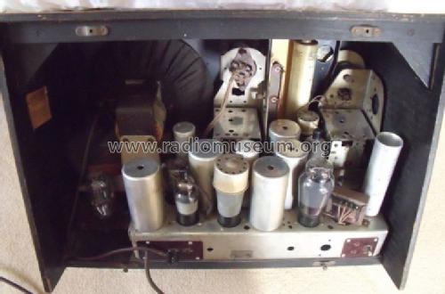
The mechanical details of the chassis are interesting. It goes without saying that the maker's reputation for neatness and sound workmanship has been maintained. Considerations of space and cabinet design have led to the mounting of the loudspeaker, mains transformer, and rectifier valve on a separate unit overhanging the edge of the chassis. Another unusual feature is the location of the output valve in the shortwave section of the chassis layout. Actually, this is the logical position for this valve as it takes its input from the shortwave RF amplifier which has been reflexed to provide the first stage of AF amplification. In a receiver of this type, special attention must be given to screening in order to avoid "pulling" of the oscillator, mediumwave pick-up when the shortwave range is in use, and mains hum. As an indication of the care which has been taken in small details, it may be mentioned that certain of the coupling components associated with the reflexed valve is actually mounted inside the screening cap on the top of the valve. In spite of its somewhat belated entry into the fold, we believe that the A36 is a receiver that will have a marked influence on the future trend of commercial short-wave broadcast receiver design.Wireless World, April 23rd, 1937, pages 400-402
Gary Cowans, 08.Mar.22