- Country
- Great Britain (UK)
- Manufacturer / Brand
- Murphy Radio Ltd.; Welwyn Garden City
- Year
- 1938
- Category
- Television Receiver (TV) or Monitor
- Radiomuseum.org ID
- 132073
Credit David Grant
Click on the schematic thumbnail to request the schematic as a free document.
- Number of Tubes
- 18
- Valves / Tubes
- SP41 ACTH1 SP41 SP41 SP41 SP41 VP41 HL41DD AC5/Pen DD41 T41 AC5/Pen T41 AC6/Pen UU4 UU4 U21 CRM91
- Main principle
- Superheterodyne (common)
- Wave bands
- Wave Bands given in the notes.
- Power type and voltage
- Alternating Current supply (AC) / 200-260 Volt
- Loudspeaker
- Permanent Magnet Dynamic (PDyn) Loudspeaker (moving coil)
- Power out
- 5 W (unknown quality)
- Material
- Wooden case
- from Radiomuseum.org
- Model: A56V - Murphy Radio Ltd.; Welwyn
- Shape
- Console with any shape - in general
- Dimensions (WHD)
- 18 x 35 x 17.5 inch / 457 x 889 x 445 mm
- Notes
-
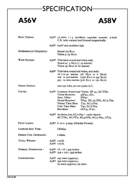
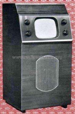
Murphy A56V; 9" round CRT (7.5 x 6") 405 lines b/w TV with GB standard 1 channel VHF band I (45 MHz) tuner, 245 watts power consumption.
Cabinet design by RD Russell.
See also TV & Radio combination, A58V.
- Net weight (2.2 lb = 1 kg)
- 119 lb (119 lb 0 oz) / 54.026 kg
- Price in first year of sale
- 30.00 £
- Source of data
- -- Original prospect or advert
- Mentioned in
- - - Manufacturers Literature (A56V, A58V Specification 079/12/38)
- Author
- Model page created by a member from A. See "Data change" for further contributors.
- Other Models
-
Here you find 367 models, 301 with images and 235 with schematics for wireless sets etc. In French: TSF for Télégraphie sans fil.
All listed radios etc. from Murphy Radio Ltd.; Welwyn Garden City
Forum contributions about this model: Murphy Radio Ltd.;: A56V
Threads: 1 | Posts: 1
MURPHY A56V
Television Receiver (15 Valves + 3 Rectifiers) for Alexandra Palace Sound and Vision Only, Price £30.
It is safe to say that the majority of prospective viewers already possess a good broadcast receiver, and if they have grown to know its little tricks of tuning and tone control and are satisfied with its quality of reproduction, they may not like the idea of having to accept a new instrument as make-weight in the new television set.
The Murphy A56V is as much a self-contained receiver as television is a self-contained service, and it can, if required, be installed in a different room from the existing broadcast set so that the two can be used simultaneously.
Murphy Radio has already had the experience of building a television receiver (the A42V) without restriction as to cost. Most of the economies they have effected in the A56V are the result of the better valves which are now available and of the acceptance of slightly smaller picture size.

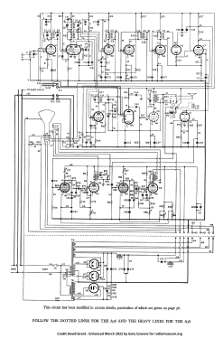
Circuit. -The dipole aerial feeder is tapped directly into the tuned aerial circuit preceding the single stage of RF amplification, which is a transformer coupled to the frequency changer. The inherent damping in the tuned circuits associated with the RF stage is sufficient to cover both sound and vision signals without tuning. There is a pre-set gain control for areas of medium signal strength consisting of a variable cathode bias resistance. In areas of strong signal strength, this is hardly sufficient to prevent 'the formation of a vertical pattern on the picture due to cross-modulation between sound and vision channels, and an additional input attenuator becomes necessary. The makers, through their service agents, are able to fit an accessory with the required attenuation when the receiver is installed.
Tuning is effected by varying the oscillator frequency. The triode section of the frequency changer is arranged as a Colpitts circuit with inductance tuning by means of an adjustable metal plunger. The normal oscillator frequency is 40.75 Mc/ s, giving intermediate frequencies for sound and vision of 750 kc/s and 4.25 Mc/s respectively.
The sound receiver is similar in general design to that of the A46 broadcast receiver but has a wider bandwidth in the IF stage to take advantage of the good quality available from Alexandra Palace and to allow for a possible drift in the oscillator frequency. The double diode-triode second detector supplies undelayed AVC to the IF valve and also acts as the first AF stage before the output tetrode. Negative feedback is incorporated in this stage.
Three stages of IF amplification is used in the vision receiver with a gain (contrast) control consisting of a variable cathode resistance in the first two stages. A tuned filter is connected in the cathode circuit of the first stage to introduce negative feedback at the frequency at which a break-through of the sound channel may be experienced. A diode rectifier follows the vision IF amplifier and feeds the single-stage vision amplifier, the anode of which is connected directly to the control grid of the cathode-ray tube. This ensures that the DC component will be retained under all conditions. The brightness control takes the form of a potentiometer in the cathode circuit of the cathode ray tube.
Segregation of the synchronising impulses is effected by a double-diode valve fed from the cathode circuit of the vision amplifying stage.
Saw-toothed currents for the magnetic deflection of both line and frame time bases are generated by gas-filled triodes in conjunction with tetrode power amplifiers. An interesting method of ensuring linearity in the working stroke of the time bases has been devised and is dealt with in " Television Topics " in another part of this issue.
The power consumption of any television set is considerably greater than that of a broadcast receiver, and in this case, two rectifiers with strapped anodes are used for full-wave rectification of the main power supply. After one stage of smoothing the current divides, one branch goes through the loudspeaker field for extra smoothing, to the sound and vision receivers, the other through the focusing coil to the time bases. Suitable decoupling is provided to prevent interaction between the various circuits.
The high tension of 4,700 volts for the anode of the cathode ray tube is derived from a separate mains transformer and a half-wave rectifier valve with a cathode of large heat capacity to delay the application of the HT voltage until the remaining circuits have warmed up. To prevent damage to the screen after the set has been switched off and while a charge remains in the HT reservoir condenser, the mains switch is provided with contacts that increase the cathode bias resistance of the tube to limit the beam current. Once the set has been switched off it should not be switched on again until the HT rectifier cathode has had a reasonable chance to cool down.
Performance.- The instrument was tested at a distance of six miles from Alexandra Palace on a dipole aerial erected well clear of surrounding buildings. The signal strength was above the optimum for satisfactory operation and the makers supplied an input attenuator to eliminate the cross-modulation between the sound and vision signals.
We were very much impressed by the reserve of brightness in the picture, which enabled it to be viewed in comfort in daylight. The contrast control was well able to cope with the corresponding adjustment required of it, and all the controls of the instrument are notable for their wide range. The line and frame synchronising controls are not critical, and once set require no further attention.
Focusing is sharp and uniform up to the edges of the picture. The focusing control required much less attention than was expected in view of the fact that it is magnetic. By the time the valves had warmed up and the synchronising controls had been properly adjusted, the focusing coil current was sufficiently stable to hold its setting for the remainder of the transmission period.
The definition is excellent and the breaking up of the lines into closely spaced dots due to some breakthrough of the vision intermediate frequency is not at all objectionable and gives the effect of a halftone reproduction. A 10", moving coil loudspeaker of the type used in the Murphy A38 receiver is employed in the sound channel and quite easily reveals the superior quality associated with transmissions from the Alexandra Palace studios.
There are rather more than the usual number of tappings on the mains transformer as the set is more sensitive to changes of HT volts than an ordinary broadcasts receiver. Errors of adjustment may be suspected if the picture is too wide or too narrow. Normally a picture size of 7½" by 6" is obtained, and this is an admirable compromise for the range of viewing distances and the number of the audience which can be comfortably accommodated in the average living room.
 Constructional Details.-The end of the tube is framed in a molded black rubber mask which is fitted over the tube itself. The chassis as a whole is hinged and in its normal position, all components under the base are readily accessible. By removing two screws the chassis may be lowered into a horizontal position for valve or tube inspection.
The cathode-ray tube passes through a hole in the chassis and the wiring of vision frequency and time base circuits is thereby reduced to a minimum. This method of construction enables a very compact cabinet to be designed as well as facilitating adjustment and servicing. All connections to the chassis, including those to the controls on the side of the cabinet, are flexible, and it is possible to work the set in the horizontal position.
Summary.-The A56V very happily fills the gap between the larger and more expensive combined television and radio receivers and the cheap table models with small tubes. In size, brightness, and quality the picture is much nearer the performance of the former than the latter class of instrument. The controls are as easy to work as they are simple in appearance. In relation to the circuit specification, the quality of components, and the performance, the price is very reasonable and appears to have been fixed in advance for future quantity production
The Wireless World, May 4, 1939, Page 422- 424.
Gary Cowans, 21.Mar.22