External VFO CQ-201
NEC Corporation, Nippon Electric Co. Ltd. (Nippon Denki); Tokyo
- Country
- Japan
- Manufacturer / Brand
- NEC Corporation, Nippon Electric Co. Ltd. (Nippon Denki); Tokyo
- Year
- 1977 ??
- Category
- Amateur Equipment (Other, but not Key)
- Radiomuseum.org ID
- 342051


From original "Instruction Manual.

From original "Instruction Manual"
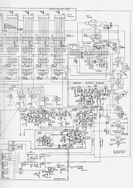
Click on the schematic thumbnail to request the schematic as a free document.
- Number of Transistors
- 28
- Semiconductors
- 2SC373 2SA495 2SA496 2SC1047 2SC372 2SC1096 2SK19 3SK35 2SK41 2SD235 SN7447 SN7475 SN7490 SN7400 SN7473 SN7404 SN7476 1S953 1N60 1S1555 10D-1
- Wave bands
- Wave Bands given in the notes.
- Power type and voltage
- Alternating Current supply (AC) / 110; 220 Volt
- Loudspeaker
- - - No sound reproduction output.
- Material
- Metal case
- from Radiomuseum.org
- Model: External VFO CQ-201 - NEC Corporation, Nippon
- Shape
- Tablemodel, with any shape - general.
- Notes
-
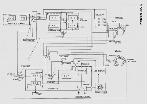
External VFO with output frequencies: VFO-A: 5.0 ÷ 5.5 MHz, VFO-B: 8.2 ÷ 8.7 MHz,
VFO-C: 8.9 ÷ 9.4 MHz.
Output Voltage: 2 V p-p. Output Impedance: 50 ÷ 100 Ω. Frequency display direct read.
This VFO may be used also as a Frequency Counter from 10 Hz to 30 MHz with input level 0.1 V (p-p) above 100 kHz and 1 V (p-p) below 100 kHz.
Three separate outputs for VFO-A, VFO-B and VFO-C.
The operating voltage is changed by moving the connections directly on the power transformer.
28 Transistors, 38 ICs and 59 Diodes, listed one per type.
Only one IC (IS3554) not present in the semiconductor list.
- Mentioned in
- -- Original prospect or advert (“Radio Rivista” official organ of "ARI Amat. Radio Assoc." of Italy, number 10, October 1977.)
- Author
- Model page created by Pier Antonio Aluffi. See "Data change" for further contributors.
- Other Models
-
Here you find 179 models, 146 with images and 17 with schematics for wireless sets etc. In French: TSF for Télégraphie sans fil.
All listed radios etc. from NEC Corporation, Nippon Electric Co. Ltd. (Nippon Denki); Tokyo