- Land
- Japan
- Hersteller / Marke
- Nitto Electric Industrial Co., Ltd.; Ibaraki, Osaka-Pref.
- Jahr
- 1955 ??
- Kategorie
- Rundfunkempfänger (Radio - oder Tuner nach WW2)
- Radiomuseum.org ID
- 306709
Klicken Sie auf den Schaltplanausschnitt, um diesen kostenlos als Dokument anzufordern.
- Anzahl Röhren
- 3
- Hauptprinzip
- Super, ZF mit Rückkopplung; ZF/IF 455 kHz; 1 NF-Stufe(n)
- Anzahl Kreise
- 4 Kreis(e) AM
- Wellenbereiche
- Mittelwelle, keine anderen.
- Betriebsart / Volt
- Trockenbatterien / 45 + AA: 2 x 1.5 Volt
- Lautsprecher
- - Ist ein Kopfhörer oder Ohrhörer
- Belastbarkeit / Leistung
- 0.0002 W (sinus/unverzerrt)
- Material
- Plastikgehäuse (nicht Bakelit), Thermoplast
- von Radiomuseum.org
- Modell: Bamby - Nitto Electric Industrial Co.,
- Form
- Kleines Reisegerät oder «Taschengerät» < 20 cm.
- Abmessungen (BHT)
- 136 x 82 x 25 mm / 5.4 x 3.2 x 1 inch
- Bemerkung
-
The output earphone should be of the Rochelle crystal type, not of the modern ceramic type. The original Rochelle crystal types are much more sensitive with an internal capacitance around 1-2nF (impedance is 160k-80kΩ at 1kHz), while modern ceramic earphones have around 20nF (impedance is 8kΩ at 1kHz) of internal capacitance. The Rochelle crystal earphone has fairly well impedance matched to the ~100kΩ output impedance of the audio stage.
- Nettogewicht
- 0.5 lb (0 lb 8 oz) / 0.227 kg
- Literatur/Schema (1)
- -- Collector info (Sammler)
- Autor
- Modellseite von Joe Sousa angelegt. Siehe bei "Änderungsvorschlag" für weitere Mitarbeit.
- Weitere Modelle
-
Hier finden Sie 4 Modelle, davon 4 mit Bildern und 1 mit Schaltbildern.
Alle gelisteten Radios usw. von Nitto Electric Industrial Co., Ltd.; Ibaraki, Osaka-Pref.
Forumsbeiträge zum Modell: Nitto Electric: Bamby
Threads: 1 | Posts: 1
Fellow Radiophiles:
In June of 2018 I visited "Radioactivity" which is the annual meet of the Mid-Atlantic Antique Radio Club outside Washington DC.
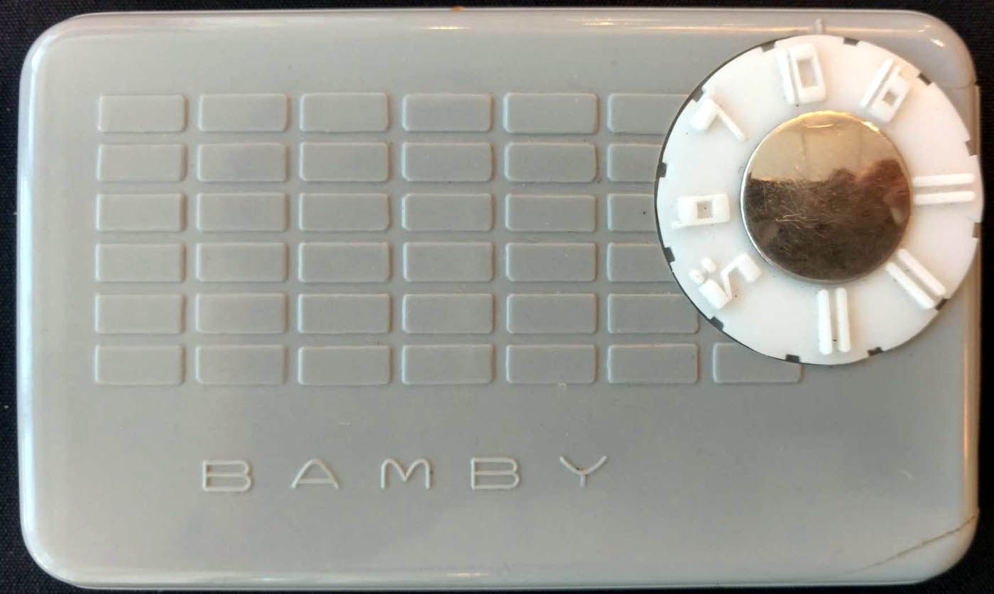
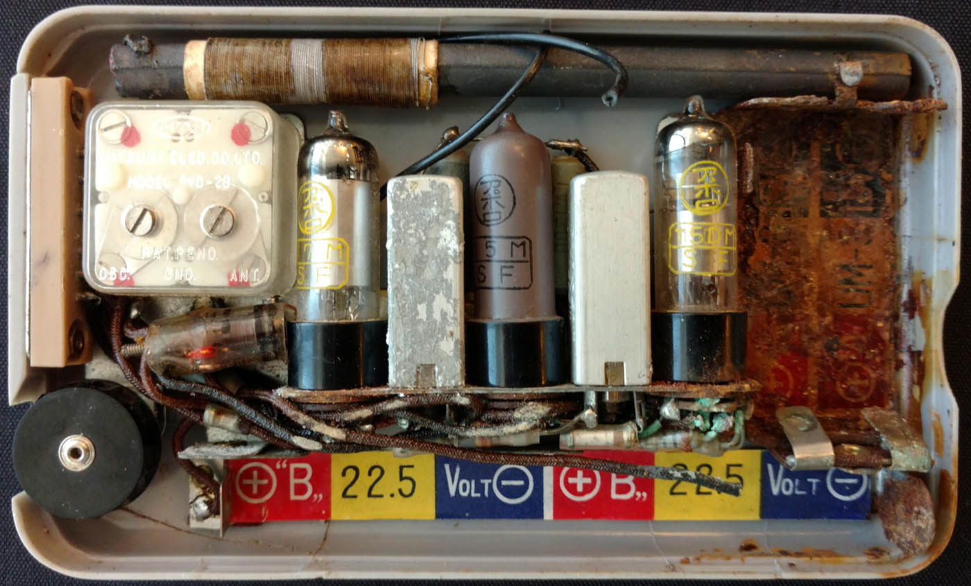
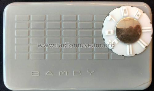
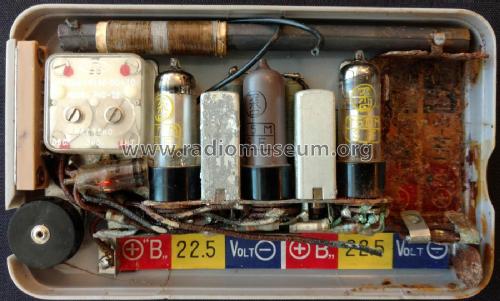
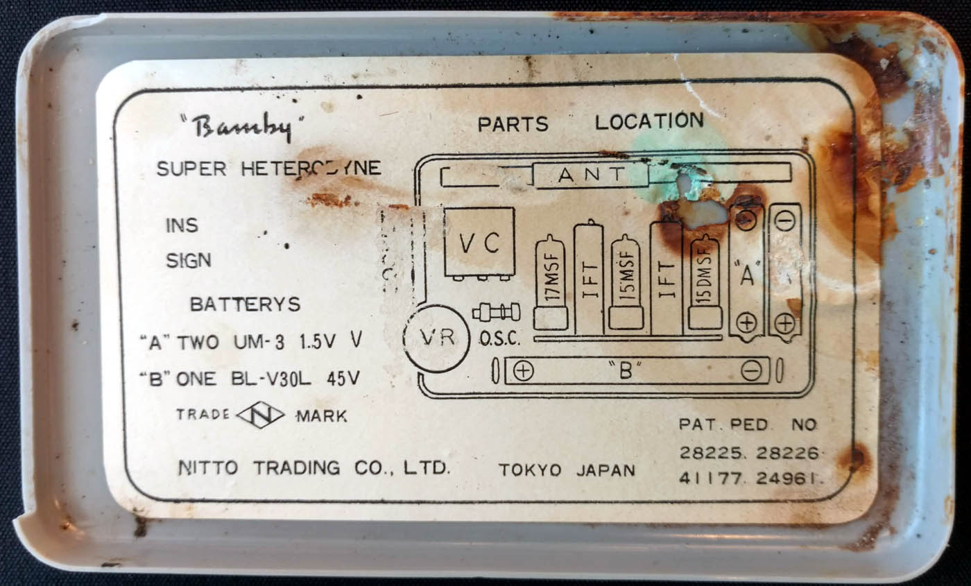 A never seen before shirt-pocket tube superhet radio from Japan named Bamby was shown in the old equipment contest at Radioactivity by Jon Hall. Jon was very kind and offered to lend me the radio to see what I could learn from it. The photos show the radio as found.
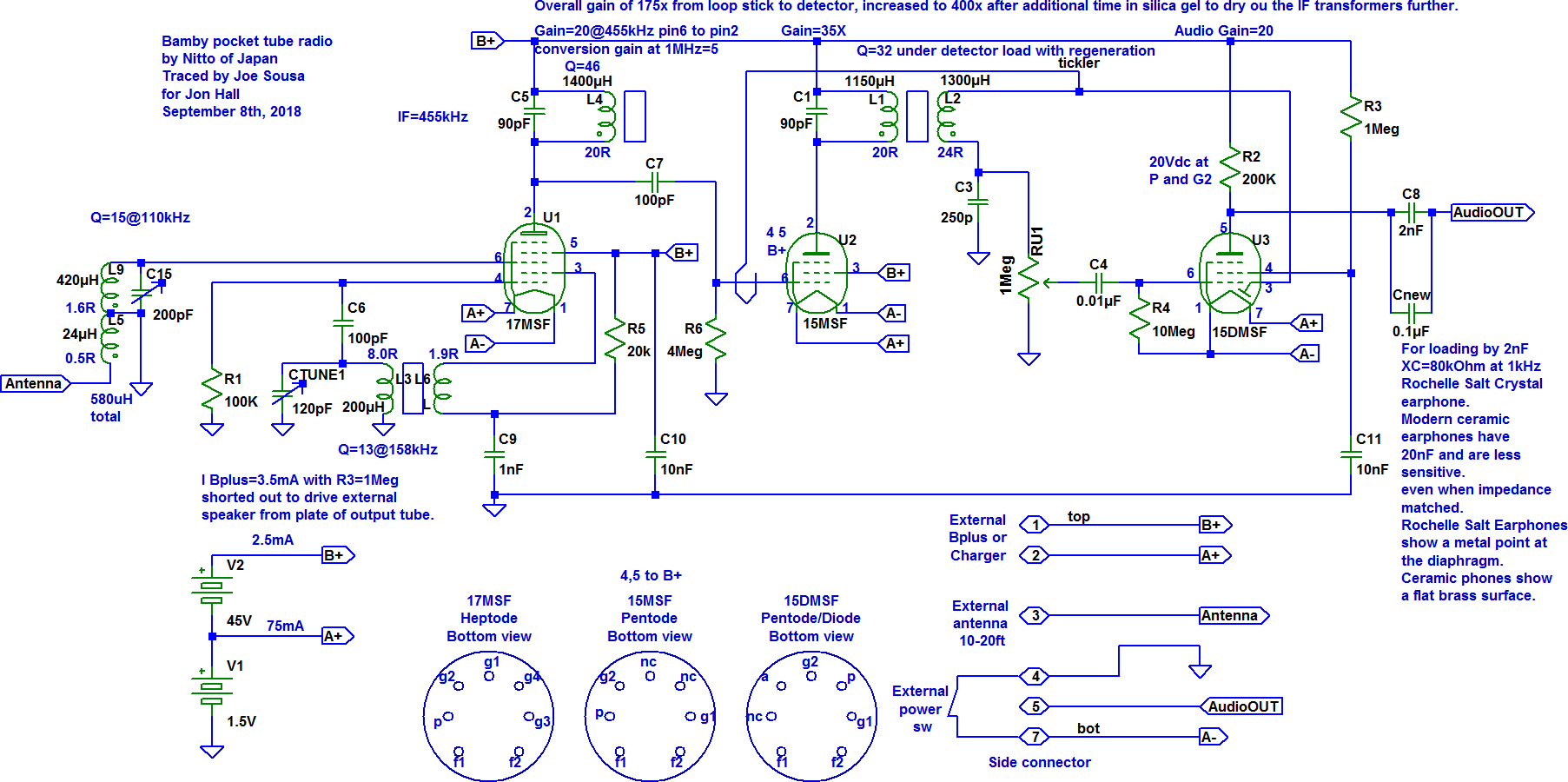
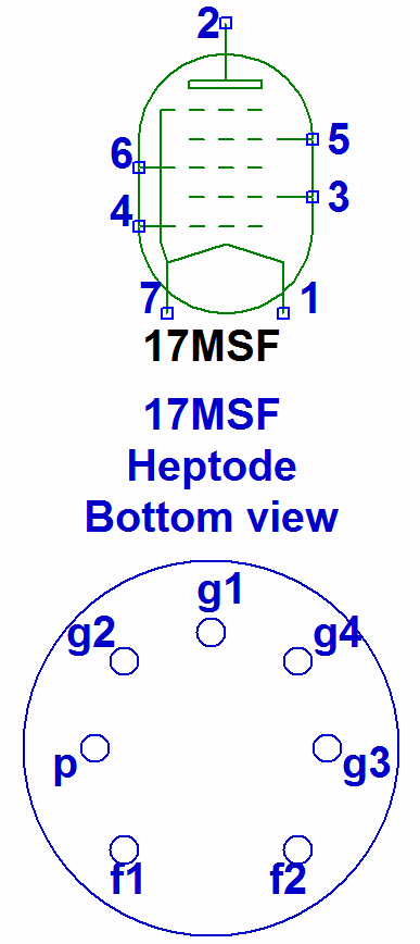
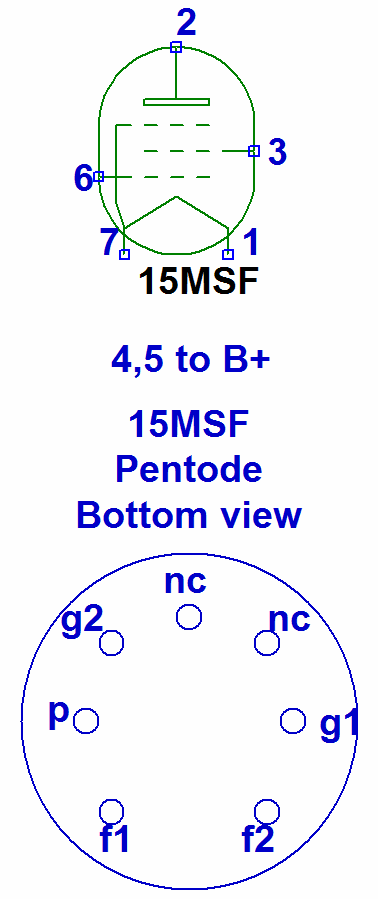
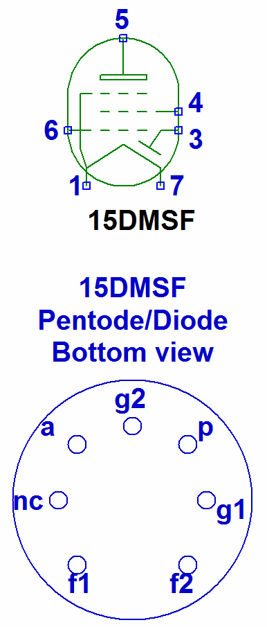
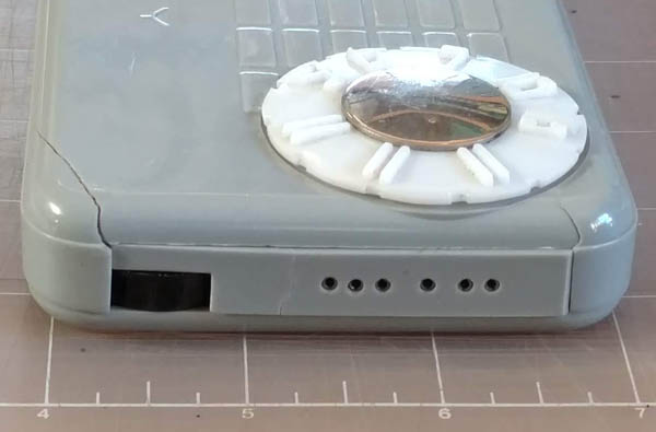
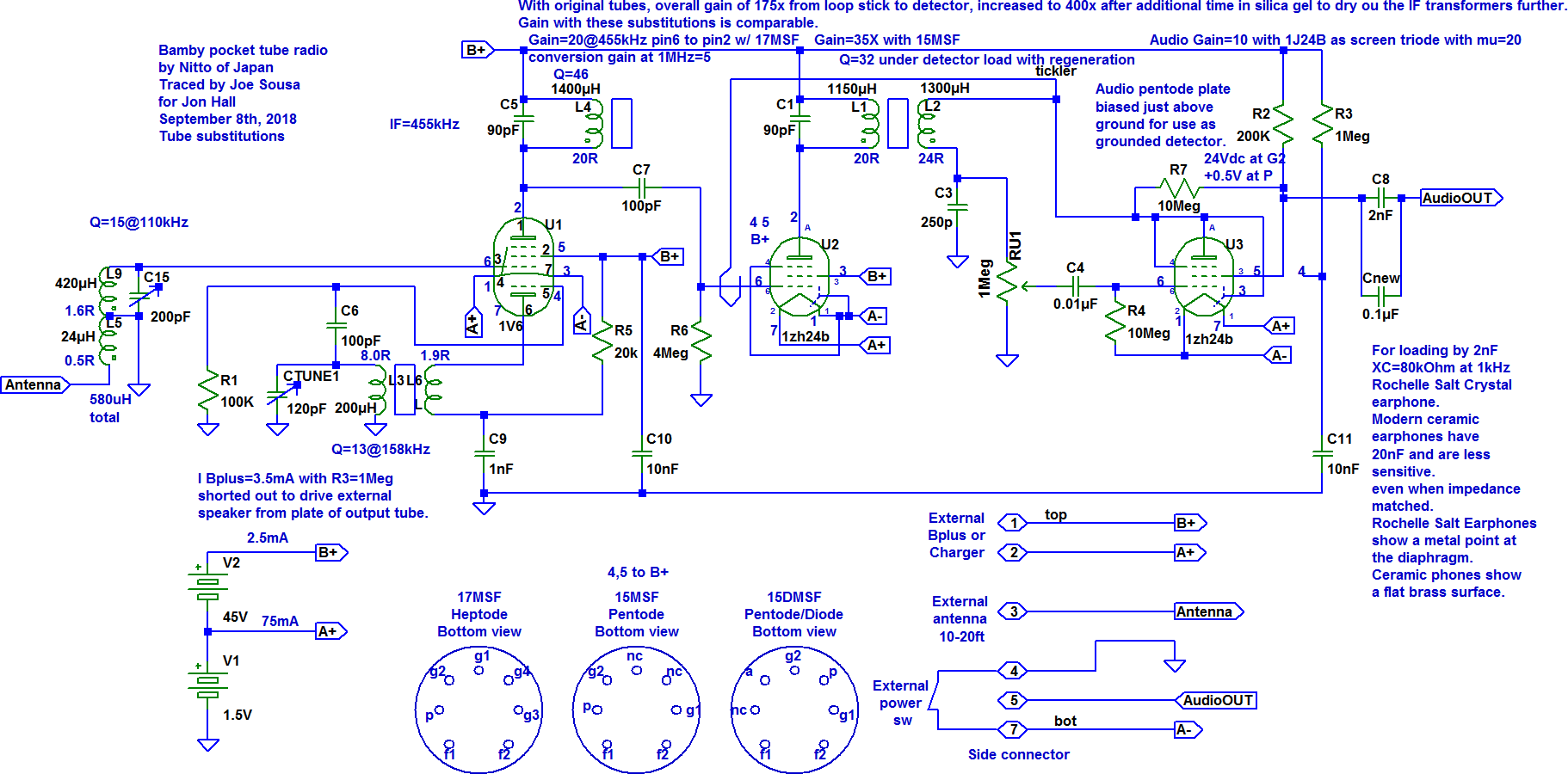
The radio was made by Nitto of Japan as shown in the internal label, probably in the mid-1950's. The set is only 5.4 inches wide and 1 inch thick. It has three tubes by Apollo of Japan that were also unknown. This pocket radio has an audio stage that was designed to drive a Rochelle Crystal earphone with an impedance in the 100kΩ (2nF) range. The earphone and the special six-pin plug fixture, that plugs in on the left side, were not with the radio. The tube complement is a 17MSF heptode as frequency converter, a 15MSF pentode as the 455kHz IF stage and a 15DMSF diode/pentode as detector and earphone audio amp.
The circuit configuration is fairly conventional, with a built-in ferrite stick antenna and provision for an external antenna connection. Even a few feet of external antenna wire help significantly without detuning the ferrite tank. There is no AGC (Automatic Gain Control) and the IF strip only has two tuned circuits instead of the customary four. There was a lot of battery corrosion, but once cleaned up and aligned, the set worked quite well with just the internal ferrite loop-stick antenna, picking up the same daytime radio stations as typical sets. The power source for the filaments is two AA carbon-zink cells in parallel to supply 75mA of filament current for the three 25mA tubes. Two 22.5V (type Eveready 505 / Neda 221A) batteries in series to create 45V to deliver 2.5mA to the plate supply.
I hand-traced the circuit after some detective work to figure out the unknown tube pinouts.
Identifying the tube pins
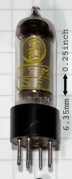

 If the tubes have good filaments and reasonable emission, there is a simple procedure to identify the various pins of almost any tube. First, the filament (or heater) pins are identified with an Ohmmeter. Then the correct filament voltage is applied. This voltage was deduced directly from the AA battery voltage that supplies the filaments as 1.5V. If this filament voltage is not known, one can compare the cold filament resistance with tubes of similar type, and increase the voltage until the resistance rises by about the same proportion as with a comparable tube. This voltage should also result in one of the common filament current values, like 25mA, 50mA, 100mA, 150mA, 300mA, 450mA, 600mA, etc. It is of course a good idea to keep an eye on the color of the filament glow to avoid accidental overdrive. These very low power tubes with only 25mA current draw from 1.5V only show some glow in complete darkness.
With the filament voltage applied, a negative space charge develops around the filament and it will charge the nearest grid with a negative voltage which may be just -100mV up to several negative volts. This voltage persists under light loading in the uA region. Now measure the voltage between the + terminal of the filament voltage and all the remaining pins. These tubes have a total of 7 pins. It is best to use a 10Meg impedance voltmeter, but a 1Meg impedance voltmeter will still work but give smaller voltage values due to the extra loading.
If the tube has a single device, like the 17MSF heptode or the 15MSF pentode, the pin that shows the most negative voltage is the control grid. If the tube has two devices, like the 15DMSF diode/pentode, the two most negative pins will be the control grid of the pentode and the anode of the diode. In the example of the 15DMSF, I tied filament pin 1 arbitrarily to +1.5V and ground filament pin 7. One of the two terminals that had strong negative voltages had -2.7V at one terminal and the other had -1.2V when measured with respect to the + terminal of the filament pin 1.
Next, tie the pin with the most negative voltage to the + terminal of the filament pin 1 and again look for the pin with the most negative voltage. If the negative terminal that you tie to the + terminal of the filament is the anode of the diode, it will have no effect on the other pin voltages and is thus identified as the anode of the diode, which is at pin 3. The anode of the diode also has the further characteristic that it is usually placed near one terminal of the filament. The voltage that develops at the anode of the diode will then be affected by the polarity of the battery voltage on the filament. The other pin with the strong negative voltage is now identified as the control grid at pin 6.
Now tie the control grid pin 6 to the + terminal of the filament pin1. Tying the control grid to the plus terminal is perfectly safe and serves to accelerate the space charge past the control grid, thus making the screen grid voltage more negative. Now the most negative pin voltage became -0.9V. This pin is now identified as the screen grid pin 4.
Now tie the screen pin to the + terminal of the filament along with the control grid pin that is already connected there. Look again for the most negative pin. This will be the plate of the pentode because there are no remaining pins. The plate of the 15DMSF had -220mV. One of the terminals never showed any voltage, so it was considered unused. This is also the reason why the suppressor grid was presumed to be tied to one of the filament pins, as is often done with filamentary pentodes.
The identification of the internal connection of the suppressor grid to one of the filament pins is not very important to draw out the schematic of the radio, but it can still be identified. When the plate pin is identified, tie all other pins to the positive terminal of the filament. Then swap the filament battery terminals and measure the plate voltage against the positive battery terminal. Identify which battery polarity gives a slightly more negative plate voltage. In this filament battery connection, the suppressor grid is tied to the positive end of the filament.
This procedure was repeated for the 17MSF heptode and 15MSF pentode. The voltages in the heptode decayed even more by the time that the plate was identified, but there was always one pin that had a measurable negative voltage. The plate of the 17MSF only had a few mV negative with a 10Meg voltmeter.
Rust removal
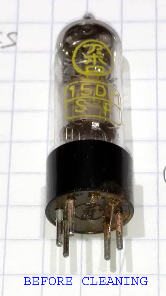
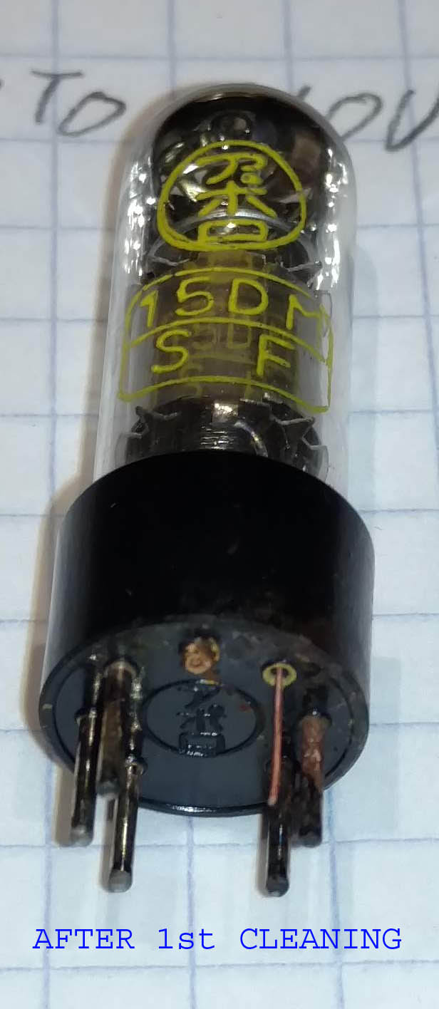
 The 15DMSF and the battery end of the chassis were heavily rusted from leaked battery electrolyte. I used "Ultra One Safest Rust Remover" on the recommendation of fellow radiophile Matthew D'Asaro. This is a mild liquid chemical that removes rust slowly. It took several hours to remove the rust from the pins of the 15DMSF, but two of it's pins were completely gone. I ended up making three new pins from 1mm brass tubing and cemented the pins inside the Bakelite socket with JB-Weld epoxy. The photos on the left show the effect of cleaning with the rust remover and the three new brass pins.
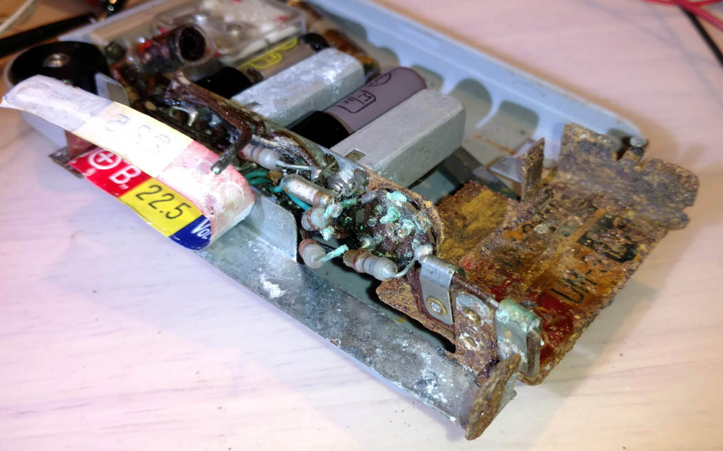
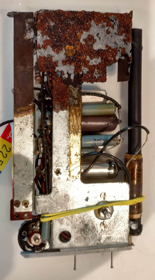

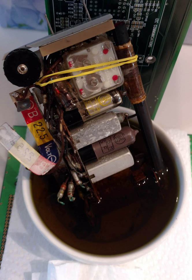 It took several days with the rusted end of the chassis dipped in the rust remover fluid to finally clean out all the rust. The fluid turned dark and was changed daily with clear fresh fluid.
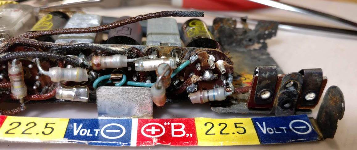 The rust removal left a few holes in the heavily corroded end of the chassis, but the chassis remained otherwise structurally sound. The label under the AA batteries was also lost to rust, but a new one might be recreated from the photos before the rust treatment. The 22.5V battery label was pealed back before the rust treatment. The rust removal eliminated a heavy 8mA power supply leakage from 45V, which was probably around the audio tube socket. Now there is zero draw from 45V with the filaments off. Two of the pin receptacles in the audio tube socket were also replaced with fresh rivets. The rivets were spot glued in place with a bit of epoxy.
Sheared Tube Wire Repair
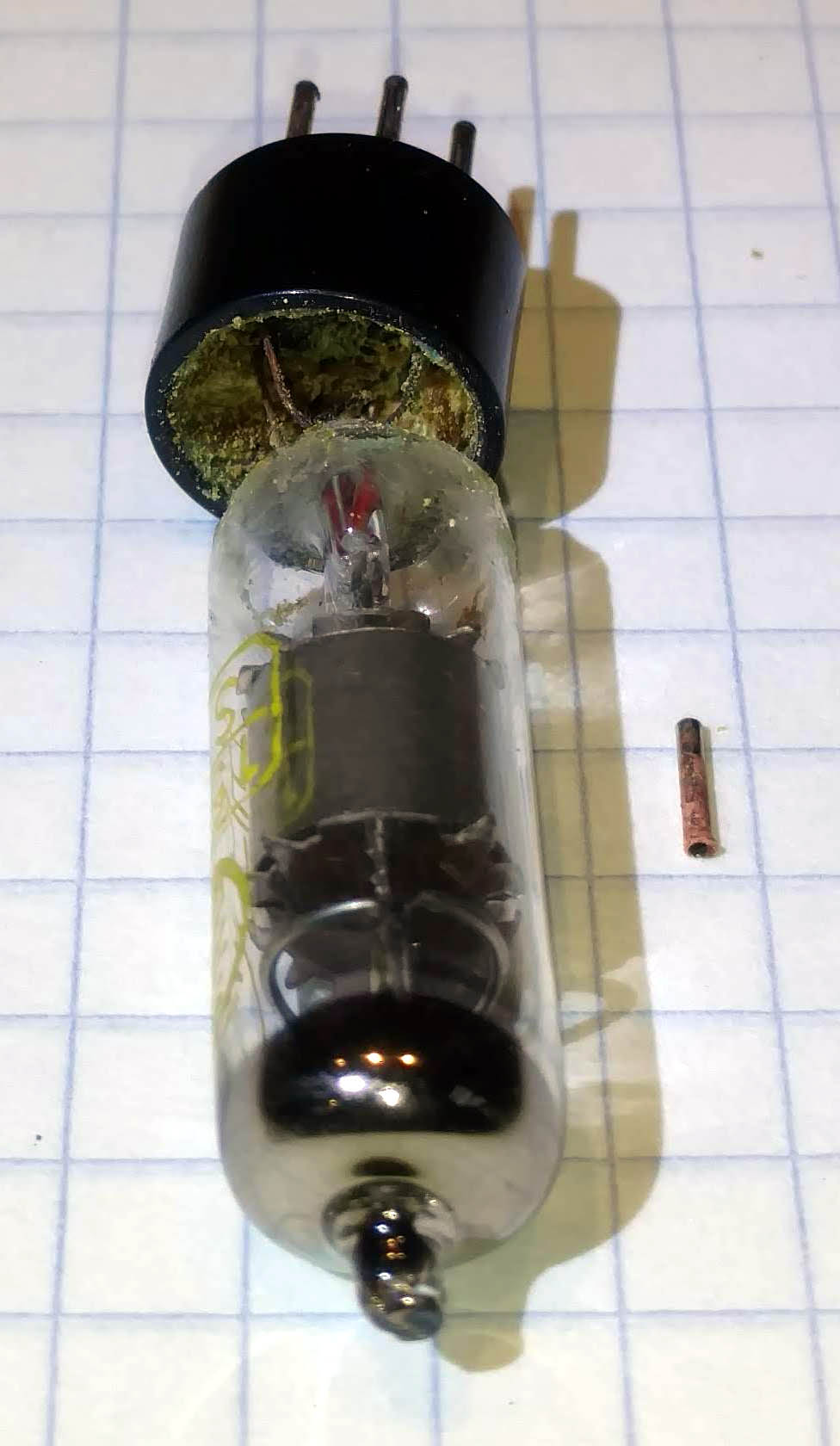
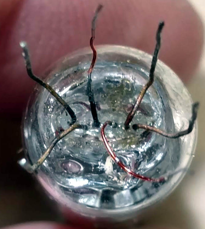 When removing the bulb from the Bakelite base, I sheared one of the filament terminals off at the glass, but was able to repair this. That wire terminal was corroded inside the pin and would not otherwise come out of the pin. The fix for the sheared terminal was to weld a new thinner wire (AWG36 or thinner) to the terminal that was slightly sunken into the glass. I made contact to it with a needle and then discharged 20V from 1000uF through the new thin copper terminal wire to weld it to the terminal flush with the glass. This came off a couple times with bending around. I settled on welding followed with a touch up of soldering and gluing down the wire to the rim of the bulb with UV cured glued to relieve stress. The new shiny copper wire is visible at the bottom right with the clear drop of glue. Now the tube works 100% and looks as good as new, except that it is probably a couple mm longer than originally. I sealed the bulb to the Bakelite socket with a bead of that clear UV cured glue.
Contaminated IF Transformer has low tank Q
 |
 |
 |
 |
 |
 |
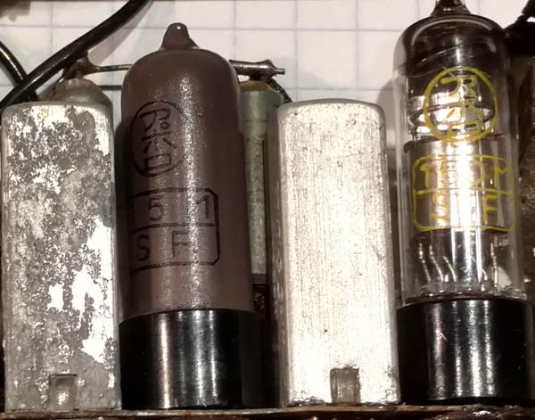
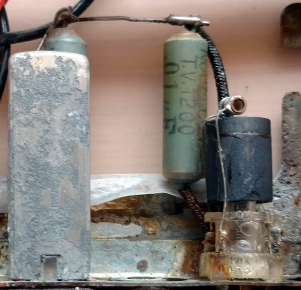
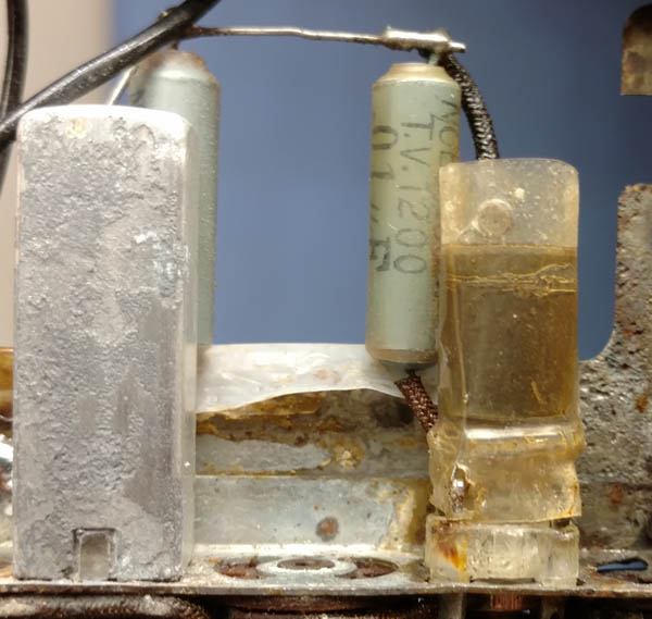
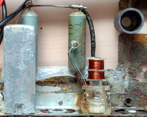
During an initial alignment of the IF transformers I noticed that the second tank was far out of alignment, resonating much below 455kHz at 300kHz and had very little effect on the IF stage frequency response. I measured the Q of the tank with a frequency sweep around 455kHz and the ratio of the peak resonant frequency to the difference between the upper and lower -3dB (70.7% of peak) points, 340kHz and 590kHz, was only 1.8. This is much lower Q than the measured Q=46 for the first IF transformer. The low Q also greatly reduces stage gain by a comparable proportion to the Q reduction.
I suspected possible electrolyte or rust remover contamination of the IF transformer coils. A first check on this hypothesis was to warm up the coil to dry it out. I applied 3V to the coil secondary, which has a 22Ω internal resistance and thus dissipate 0.4Watt for 10 minutes and the coil temperature rose 20oC as could be inferred from the increase in DC resistance from 22Ω to 23.5Ω. This dried the coil out enough that the Q rose to about 2.9. Next I put the whole pocket radio in a sealed container with freshly baked silica gel overnight to remove as much moisture as possible from the transformer coil. This raised the Q to around 32. But after a few days, moisture was reabsorbed into the coils of the IF transformer and the transformer detuned and it's Q dropped again substantially. Moisture with contamination salts is conductive and water has a huge complicated dielectric constant. This would explain the loss of Q and detuning to a lower frequency.
The final solution to the IF transformer contamination was to wash the coils with distilled water as shown in the last IF transformer figure above. Now the 2nd IF transformer stays aligned and maintains a Q=38, even on rainy days.
Operational details
The very low 25mA filament current draw of the 17MSF, 15MSF and 15MSDF place these tubes among the most efficient of their era. The 15MSF pentode in Bamby is comparable to the contemporary DF96 pentode, which draws also 25mA of filament current with about the same transconductance. The transconductances of the 15MSF and DF96 are 520uS with 39V at the plate and screen grids vs 650uS with 45V at the plate respectively.
The absence of AGC makes for very large variations in volume from station to station. But, despite the lack of AGC, the strong local station (WRKO 680kHz 50kW) that is only 4 miles away was very loud, but without distortion and did not bleed into the weak (WJIB 740kHz 250W) some 14 miles away. It is virtually certain that if Bamby were less than 1 mile from WRKO, it would produce distortion, unless the ferrite antenna were rotated to reduce signal pickup to an undistorted level. The directionality of the ferrite antenna makes it practical to eliminate AGC, which may have reduced volume for mid-level signal stations.
The IF is tuned with a single tank in the first stage and a single tank transformer in the second stage. It is not possible to tune the secondary of the IF transformer separately because the primary and secondary are very tightly coupled as seen in the stacked bobbins in the photo above.
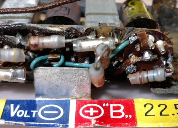 A bit of regenerative feedback is employed with a green wire loop from the detector anode pin 3 seen on the right side of the picture, that is then clipped down and loosely wrapped around the pentode control grid pin 6 of the IF pentode on the left of the picture. The little green wire can be flexed up and down over the pentode control grid pin 6 to get enough regeneration to increase gain and selectivity without oscillation.
With the tickler in place the net Q of the IF transformer circuit is maintained, despite loading by the detector. The regeneration through the tickler compensates for the loading of the detector circuit.
The resonant frequency of the IF tanks was unknown. I settled on 455kHz because it gave good tracking of the ferrite and local oscillator alignment over the AM band tuning range.
One odd unsolved mystery is that the top frequency that could be tuned was only 1.4MHz, while the tuning knob shows a top tuning frequency of 1.6MHz. I don't think this would improve with just a lower IF, as the resonant IF frequency would have to drop by 200kHz to get to 1.6MHz on the dial. The LO coil might be tuned lower, but the coil on the ferrite loop-stick is glued on.
Rochelle Crystal Earphones vs modern Ceramics
The quality audio is particularly nice because of the relatively wide bandwidth with only three tanks band-limiting the signal. I found out with my "SDRplay" Software Defined Radio that most AM music stations in my area in eastern Massachusetts broadcast with a 10kHz bandwidth. A typical AA5 set (All-American-5 AC-DC AM tube radio) with 5 tanks only has about 3kHz of bandwidth as many students measured in Ron Roscoe's radio lab course at MIT.
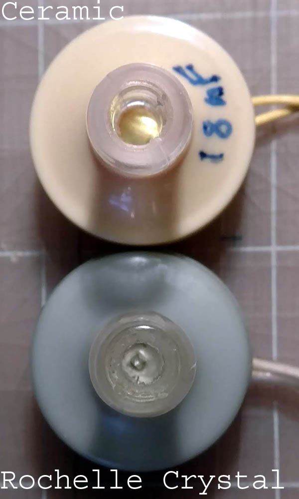 Bamby gave me an opportunity to compare the various "crystal" earphones I own. I have a few old ones that use actual Rochelle crystals and have about 2nF of internal capacitance. These are easily identified by the sharp metal point that is visible through the ear plug. The modern ceramic replacements that sometimes say "crystal" on them show a smooth metal surface through the ear plug and are only 10% as sensitive with about 20nF of internal capacitance and comparable volume at the same voltage. The ~100k audio output impedance of Bamby requires a true crystal earphone for full volume. The volume control had to be turned down on the medium to high power stations. A modern ceramic earphone is much quieter. I have looked for more of the Rochelle crystal types of earphone but they are hard to find. They are probably easiest to find with crystal radios from Radio shack that are at least 30 years old. I own about 5 Rochelle crystal earphones. One is gray as shown in the photo and is branded SONY and is the most sensitive and loudest with 1.7nF of internal capacitance. The others have reduced capacitance in the 600pF to 1nF range. I imagine that these degraded over time because Rochelle salt is very hydrophilic and often decays over time. The poor performance of the ceramic earphones was helped some by resonating with a 14H inductor I had on hand. This raised the impedance with a soft low resonance at 300Hz and doubled the audio volume. The low Q of the inductor limited the resonance boost. The ceramic earphone has a measured Q=38 at 1kHz.
The output of the audio stage has a 2nF coupling capacitor, which is adequate for a Rochelle Crystal earphone, but too low for the 17nF load of a ceramic earphone. I added a 0.1uF in parallel with the 2nF cap to make the radio usable with ceramic earphones.
Tube Substitutes
As I was finishing my work on Bamby, the work ended abruptly when trying to remove the last of the three tubes for curve tracing, a slip of the screwdriver blew out all filaments! The set very stupidly still had with the two 22.5V batteries in place. Fortunately, I had already curve-traced the last tube a few weeks earlier, so I have curve traces uploaded in RadioMuseum for the three tube types.
Bamby's owner, Jon Hall, was very kind and sympathetic and even thanked me for the rest of the work I had done. Thank you Jon!
After the disaster I set about replacing the three dead tubes with comparably functioning new ones. I settled on the versatile 1V6 to replace the 17MSF heptode and the 1j24b Russian rod pentode to replace the 15MSF pentode and the 15DMSF diode/pentode. After I got the tubes working well, I settled on surface-mount solid state replacements made with the LND150 depletion NMOSFET from Microchip, that could be hidden while the dead tubes remained in place.


 Bamby works as well as before with this tube substitution. The photo shows the construction of tube headers with 1mm brass tube pins and a body made from Quick JB-weld epoxy. This epoxy has the consistency of frosting and was just right to make the little 7 pin tube bases. Scotch tape kept the JB-weld epoxy from sticking to the pin straightening fixture. The photo also shows a cutting jig for the tube pins to get the length consistently cut with a cutting wheel in my Dremel.
The 1V6 has a pentode to one side of it's filament and a triode to the other side of it's filament. The triode is meant to be used for the local oscillator. It's control grid serves as gamma control plate for the pentode on the other side of the filament for use as the mixer. The RF input is the control grid of the pentode. Follow the 1V6 link for more details on the tube. The 1V6 was a very good electrical fit.
The 1J24B is doing what it was designed for in the IF stage and worked without trouble. The copper shield around tube bulb is necessary to achieve the required low Miller capacitance and avoid oscillations. The 1V6 and 1J24B both have lower internal cpacitances than the original Japanese tubes such that the IF tank resonance increased from 455kHz to 475kHz. I touch up in the IF alignment fixed this.
The 1j24b detector/audio substitution gave me the excuse to try a trick I figured out a while back. The plate and suppressor grid of the 1j24b are wired together and biased at 2uA with a 10MΩ pull-up to the 20V audio output. The screen and control grids are wired as the audio amplifier triode. This triode configuration has a mu=20, which yielded a stage gain of 10 with 100uA cathode current and 200k load. This is a bit lower than the gain of 20 of the original pentode, but adequate.
The plate of the pentode works at the start of it's curve family, where it looks like a diode with a ground cathode. All this works quite well without distortion. The 2uA pull-up helps bias the plate for best detection efficiency. Even with a very strong local station that develops 5V at the detector, this only pushes the plate current to 12uA, which does not leave the diode portion of the curve family on the lower left of the plot with the 1j24b curve family run with 25V at the screen as in Bamby.
The negative audio feedback imparted by the 10Meg bias resistor from the audio output simply helps sharpen the detection curve. Even though the audio feedback is negative, it actually regenerates the detection current at audio rates. See "Detection and AGC in a 5 tube AC/DC radio" for more details on the effect of negative audio feedback on the detector.
Solid State Tube Substitutes

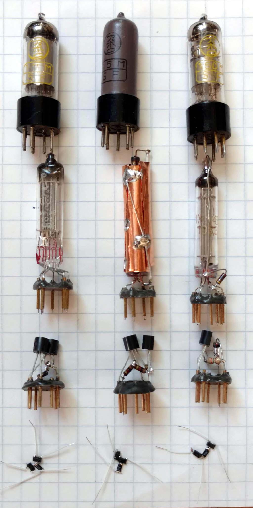 The photo shows the original 17MSF, 15MSF and 15MSDF tubes at the top, the tube substitutions in the second row followed by the LND150 in TO-92 packages in sockets and finally the LND150 in SOT.
The LND150 depletion mode NMOSFET has gm=1mS and pentode-like voltage gain in the thousands, but high triode-like 0.5pF Miller capacitance. A source-coupled pair works as the converter front end with one half of the pair as the local oscillator and the other half as the mixer. Similar to the 1V6 scheme. The IF stage has a cascoded pair to get the 0.5pF Miller capacitance down to the required 0.005pF level to avoid oscillations.
The Schottky detector has a very high impedance with zero signal, which makes the loading on the tank and the regeneration level signal dependent, producing occasional bursts of oscillation in response to audio peaks. A 100k load resistor was added in parallel with the IF transformer secondary to guaranty a minimum load on the tank. The original thermionic detector had a self-bias voltage of nearly a volt which kept a minimum bias and load on the IF tank in the hundred kΩ region.
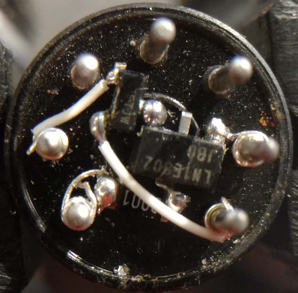 The original tubes stayed in place and the SOT MOSFETs were wired in with very fine AWG30 wire in parallel with the dead tubes. In the case of the 15MSF IF pentode in the photo, they were wired to the tube pins to minimize additional Miller capacitance from the plate to control grid. In the case of the 17MSF heptode converter and the 15DMSF audio pentode and detector, they were wired under the tube sockets. A 1n34 Germanium crystal diode was first used as the detector, but a smaller surface-mount Schottky diode was used in the end to save space.
One difference in the operation with transistors vs tubes is that simply turning off the 1.5V filament battery power only lowers the total solid state current just under 3mA to about 0.5mA. This is due to the Source-Gate ESD protection when the source floats with the filament power off and the drain and source remain strapped across 45V.
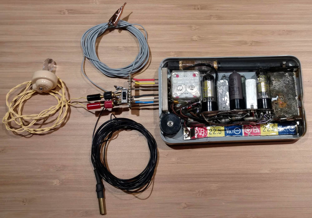
The final photo shows all the dead tubes in place with the solid state substitutions wired in the parallel. The improvised plug connects the earphone, filament power switch, Antenna wire and ground wire. Now the radio works completely, again.
During the work with this radio a number of fellow American radiophiles helped via email correspondence. They were:
-Jon Hall - Owner of Bamby and collector of many kinds of small tube and early transistor radios and very gracious supporter through this adventure.
-Robert Lozier - Experienced and well known master restorer of extremely degraded early radios.
-Ed Lyon - editor of "Radio Age", the monthly newsletter of the MAARC Mid-Atlantic Antique Radio Club. Ed wrote a pair of articles on my work on Bamby in the September 2018 and November 2018 issues of Radio Age.
-Hisashi Ohtsuka - Japanese collector who identified the rare tubes as being made by Appolo of Japan.
-Matthew D'Asaro - a young and very serious collector and restorer of old technology.
-Ron Roscoe - After many years of collecting, Ron taught an RF lab course at MIT that included restoration and analysis by each student of an old radio.
Thank you, fellow radiophiles for your support in the extraordinary adventure that was the restoration and analysis of Bamby.
-Joe
Anlagen
- j_nitto_Bamby_sch (73 KB)
- Tube Substitutions (68 KB)
- Solid State Substitutions (74 KB)
Joe Sousa, 30.Dec.18
