- Country
- United States of America (USA)
- Manufacturer / Brand
- Philco, Philadelphia Stg. Batt. Co.; USA
- Year
- 1938
- Category
- Car Radio, perhaps also + sound player/recorder
- Radiomuseum.org ID
- 51240
Click on the schematic thumbnail to request the schematic as a free document.
- Number of Tubes
- 7
- Main principle
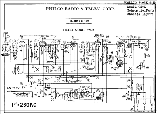
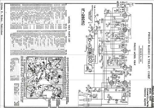
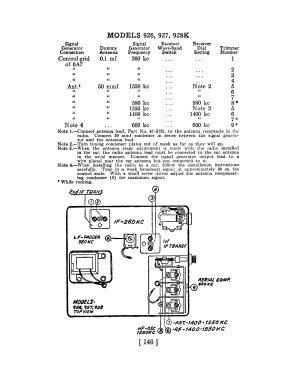
- Superhet with RF-stage; ZF/IF 260 kHz
- Wave bands
- Broadcast only (MW).
- Power type and voltage
- Storage Battery for all (e.g. for car radios and amateur radios)
- Loudspeaker
- Electro Magnetic Dynamic LS (moving-coil with field excitation coil)
- from Radiomuseum.org
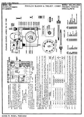
- Model: 928K - Philco, Philadelphia Stg. Batt
- Notes
- This model is equipped with a vibrator for the generation of B+.
- External source of data
- Ernst Erb
- Circuit diagram reference
- Rider's Perpetual, Volume 9 = 1938 and before
- Other Models
-
Here you find 4093 models, 2225 with images and 3741 with schematics for wireless sets etc. In French: TSF for Télégraphie sans fil.
All listed radios etc. from Philco, Philadelphia Stg. Batt. Co.; USA
Forum contributions about this model: Philco, Philadelphia: 928K
Threads: 1 | Posts: 1
Fellow Radiophiles,
In a recent email exchange with Ed Lyon (editor of Radio Age) about the application of negative feedback (NFB) from the speaker output to the cathode of a detector-diode/triode in an AM radio, Ed recalled his experience with this type of circuit in a PHILCO 928k from his repair notes.
The email exchange was, in part, related to some experimentation I reported here with this type of feedback a couple of years ago. For an explanation of how the same feedback path is negative for audio, but positive for detection, refer back to Detection and AGC in a 5 tube AC/DC radio.
Two email messages from Ed:

Another noteworthy aspect of this radio is the Push-Pull output stage that requires no additional phase inverter. The inverted signal for the lower tube is collected from the screen of the upper tube. Prof Rudolph has posted an overview of Phase-Inverters in English and Phasenumkehrstufen in German.
Regards,
-Joe
Joe Sousa, 05.Mar.10