22RB271 /00L /00S
Philips; Eindhoven (tubes international!); Miniwatt
- País
- Holanda
- Fabricante / Marca
- Philips; Eindhoven (tubes international!); Miniwatt
- Año
- 1967
- Categoría
- Radio - o Sintonizador pasado WW2
- Radiomuseum.org ID
- 80261


service manual

N°19 NL_Philips_22RB271-002_SCOV
Haga clic en la miniatura esquemática para solicitarlo como documento gratuito.
- Numero de valvulas
- 3
- Numero de transistores
- 2
- Principio principal
- Superheterodino en general; ZF/IF 452/10700 kHz
- Número de circuitos sintonía
- 6 Circuíto(s) AM 9 Circuíto(s) FM
- Gama de ondas
- OM, OL y FM
- Tensión de funcionamiento
- Red: Corriente alterna (CA, Inglés = AC) / 110; 127; 220 Volt
- Altavoz
- Altavoz dinámico (de imán permanente)
- Potencia de salida
- 1.5 W (unknown quality)
- Material
- Plástico moderno (Nunca bakelita o catalina)
- de Radiomuseum.org
- Modelo: 22RB271 /00L /00S - Philips; Eindhoven tubes
- Forma
- Sobremesa de botonera.
- Ancho, altura, profundidad
- 380 x 157 x 172 mm / 15 x 6.2 x 6.8 inch
- Anotaciones
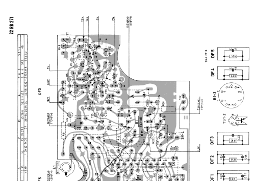
- Transistors in FM tuner. Diodes: OA90; BA102; 2x AA119. Rectifier: B250/C100. Dial lamp: 8024/71 (6,3V/0,32A). Manufactured in two colors: ../00L (red); ../00S (beige).
- Procedencia de los datos
- -- Original-techn. papers.
- Autor
- Modelo creado por Hugo Sneyers. Ver en "Modificar Ficha" los participantes posteriores.
- Otros modelos
-
Donde encontrará 5279 modelos, 4427 con imágenes y 3461 con esquemas.
Ir al listado general de Philips; Eindhoven (tubes international!); Miniwatt