- Paese
- Olanda
- Produttore / Marca
- Philips; Eindhoven (tubes international!); Miniwatt
- Anno
- 1933
- Categoria
- Radio (o sintonizzatore del dopoguerra WW2)
- Radiomuseum.org ID
- 123177


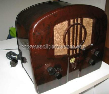
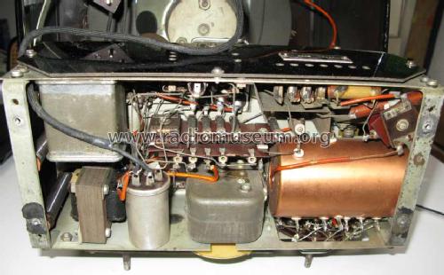
from an Ebay.fr auction in 2007
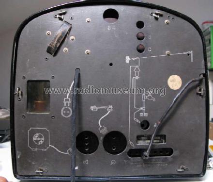
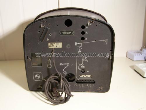
from an Ebay.fr auction in 2007

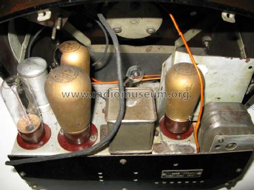
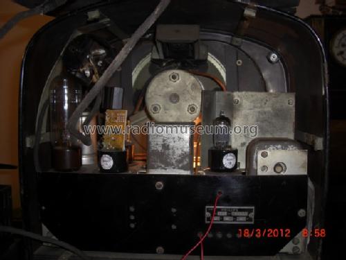
from an Ebay.fr auction in 2007

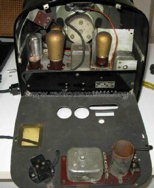
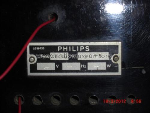
from an Ebay.fr auction in 2007


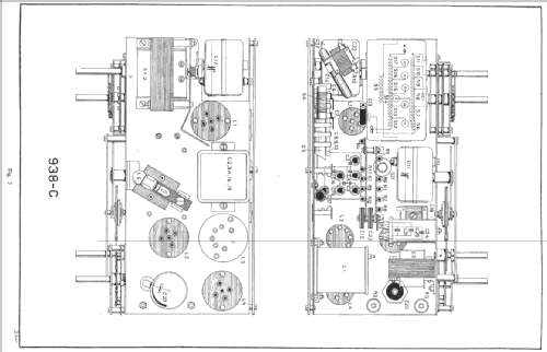
Clicca sulla miniatura dello schema per richiederlo come documento gratuito.
- Numero di tubi
- 3
- Principio generale
- A reazione (con rigenerazione); 2 Stadi BF
- N. di circuiti accordati
- 1 Circuiti Mod. Amp. (AM)
- Gamme d'onda
- Gamme d'onda nelle note.
- Tensioni di funzionamento
- Alimentazione a corrente continua (CC) / 110-130; 130-200; 200-250 Volt
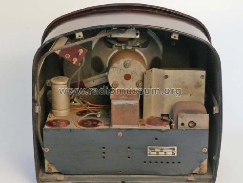
- Altoparlante
- AP magnetodinamico (magnete permanente e bobina mobile) / Ø 17 cm = 6.7 inch
- Materiali
- Speciale materiale, descritti nelle note.
- Radiomuseum.org
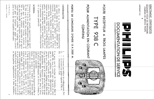
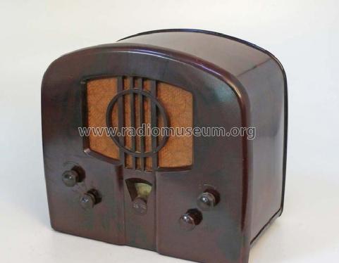
- Modello: 938C - Philips; Eindhoven tubes
- Forma
- Soprammobile basso, con andamento orizzontale (grosse dimensioni).
- Dimensioni (LxAxP)
- 320 x 350 x 220 mm / 12.6 x 13.8 x 8.7 inch
- Annotazioni
-
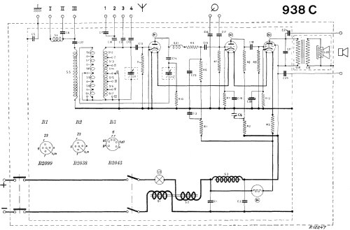
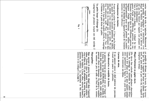
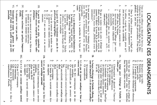
Reaction coils with fixed position; feedback regulated by C13.Grid Detection done by first tube B2099.LW, BC and SW are divided in 6 ranges:
- I. 15-33 m.
- II. 32-90 m.
- III. 85-200 m.
- IV. 200-400 m.
- V. 400-950 m.
- VI. 950-2000 m.
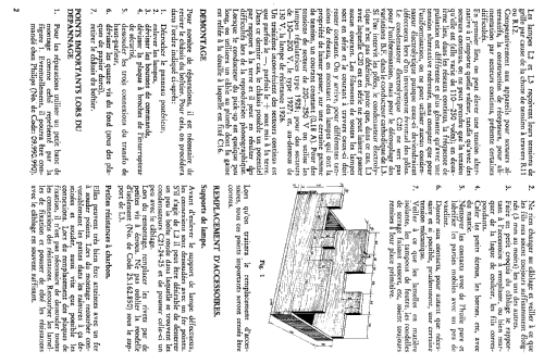
Housing in Arbolite, front panel in Philite (Bakelite).The type of resistance tube is depending on the mains voltage:- type 1926: 110-130 Volt.
- type 1927: 130-200 Volt.
- type 1928: 200-250 Volt.
- Peso netto
- 9.5 kg / 20 lb 14.8 oz (20.925 lb)
- Prezzo nel primo anno
- 1,250.00 FF
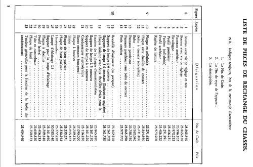
- Letteratura / Schemi (1)
- -- Original-techn. papers.
- Autore
- Modello inviato da Jean-Louis HEYD. Utilizzare "Proponi modifica" per inviare ulteriori dati.
- Altri modelli
-
In questo link sono elencati 5278 modelli, di cui 4426 con immagini e 3461 con schemi.
Elenco delle radio e altri apparecchi della Philips; Eindhoven (tubes international!); Miniwatt
Collezioni
Il modello fa parte delle collezioni dei seguenti membri.