Improved SW Booster No. 231
Postal Radio, New York
- Pays
- Etats-Unis
- Fabricant / Marque
- Postal Radio, New York
- Année
- 1935
- Catégorie
- Amplificateur HF
- Radiomuseum.org ID
- 354578


Cliquez sur la vignette du schéma pour le demander en tant que document gratuit.
- No. de tubes
- 3
- Principe général
- Amplification haute fréquence (seulement)
- Gammes d'ondes
- OC uniquement
- Tension / type courant
- Alimentation Courant Alternatif (CA) / 110 Volt
- Haut-parleur
- - - Pas de sortie basse fréquence
- Matière
- Boitier métallique
- De Radiomuseum.org
- Modèle: Improved SW Booster No. 231 - Postal Radio, New York
- Forme
- Modèle de table générique
- Remarques
-
The Postal Improved SW Booster No. 231 has the following features:
- Two-Stage SW TRF Preselector-Booster for TRF or Superheterodyne SW radios.
- Boosts the tuned SW signal, which is then connected to the SW radio antenna input.
- SW frequency is tuned with the booster's TRF 2-gang tuning capacitor and tuning coils. SW Radio should be tuned to the same SW band and frequency as the booster.
- Front panel SW TRF tuning coils are removable to select the SW bands (assumed the same as the earlier model):
- "A" 14-29 meters (10.3-21.4 MHz)
- "B" 29-55 meters (5.4-10.3 MHz)
- "C" 55-90 meters (3.3-5.4 MHz)
- "D" 90-200 meters (1.5-3.3 MHz)
- Powered by 110V AC.
- Power switch: On / Off.
- Volume control.
- Rear terminals: Antenna In +, Antenna In -, GND.
- Shielded cable pigtail to the SW radio: Antenna Out, GND.
- Antenna Select switch: Booster On (Antenna In + to booster, booster output to Antenna Out) / Bypass (Antenna In + direct to Antenna Out).
This model was an improvement over the earlier model for the following reasons:
- AC power now applied through a power transformer, which isolates AC Line and Neutral/GND from the chassis/GND, eliminating a possible AC shorting issue as described in the earlier model page.
- Higher B+ voltage to about 200V (from 90V) for greater gain and selectivity.
- Air vents added to the cabinet sides.
The earlier model was the Postal Short-Wave Booster.
- Schémathèque (1)
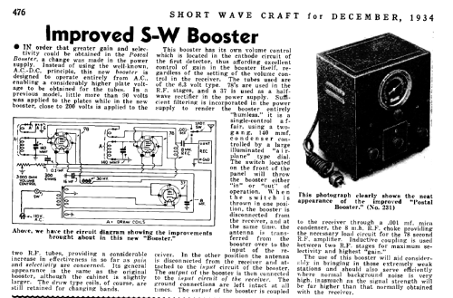
- -- Original prospect or advert (Short Wave Craft, December 1934, page 476 schematic and description, 491 ad.)
- Schémathèque (2)
- Radio Craft (January 1935, page 410 schematic and description.)
- Auteur
- Modèle crée par Jerry Elarton. Voir les propositions de modification pour les contributeurs supplémentaires.
- D'autres Modèles
-
Vous pourrez trouver sous ce lien 10 modèles d'appareils, 4 avec des images et 4 avec des schémas.
Tous les appareils de Postal Radio, New York