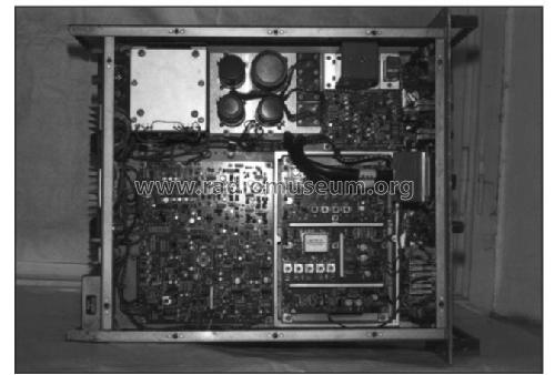
Transmitter Drive Unit MA1720
Racal Engineering / Instruments / Electronics Ltd., Bracknell
- Country
- Great Britain (UK)
- Manufacturer / Brand
- Racal Engineering / Instruments / Electronics Ltd., Bracknell
- Year
- 1977 ??
- Category
- Commercial Transmitter (TX not Transceiver)
- Radiomuseum.org ID
- 109259


Click on the schematic thumbnail to request the schematic as a free document.
- Number of Transistors
- 201
- Semiconductors
- Wave bands
- Wave Bands given in the notes.
- Power type and voltage
- Alternating Current supply (AC) / 200-250 Volt
- Loudspeaker
- - - No sound reproduction output.
- Material
- Metal case
- from Radiomuseum.org
- Model: Transmitter Drive Unit MA1720 - Racal Engineering /
- Shape
- Tablemodel, with any shape - general.
- Dimensions (WHD)
- 483 x 178 x 508 mm / 19 x 7 x 20 inch
- Notes
-
Covers the frequency range 1 to 29.9999 MHz disposing of 289,999 channels in 100 Hz steps. The channel frequency has chosen by 6 contraves selectors that set the chosen frequency without the need for further operations.
Power output can be chenged fro 25 mW to a maximum of 200 W on 50 Ω impedance.
Modes USB/LSB, AM, ISB, MCW, CW, RTTY. Can be remotely controlled.
RF Pout 0,2 W ÷ 200 W.
BF frequency range: 300 to 3,000 Hz.
The installed instrument can check: Input line level; Amplifier line; RF output voltage and internal power supply.
MA 1720 can operate on airplanes at a maximum height of 3,000 meters or on ships.
- Net weight (2.2 lb = 1 kg)
- 19.5 kg / 42 lb 15.2 oz (42.952 lb)
- Source of data
- - - Data from my own collection
- Mentioned in
- -- Original-techn. papers.
- Literature/Schematics (1)
- Radiokit Elettronica, Mar 2003 - Article "RACAL MA 1720" by Umberto Bianchi
- Author
- Model page created by Roy Johnson. See "Data change" for further contributors.
- Other Models
-
Here you find 113 models, 62 with images and 18 with schematics for wireless sets etc. In French: TSF for Télégraphie sans fil.
All listed radios etc. from Racal Engineering / Instruments / Electronics Ltd., Bracknell