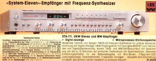
STA-111 Cat. No.= 31-2002
Radio Shack (Tandy, Realistic, Micronta); USA
- Produttore / Marca
- Radio Shack (Tandy, Realistic, Micronta); USA
- Anno
- 1982/1983
- Categoria
- Radio (o sintonizzatore del dopoguerra WW2)
- Radiomuseum.org ID
- 146027
- Numero di transistor
- A semiconduttori.
- Semiconduttori
- Principio generale
- PLL, Phase-locked loop
- Gamme d'onda
- Onde medie (OM) e MF (FM).
- Tensioni di funzionamento
- Alimentazione a corrente alternata (CA) / 117/220 Volt
- Altoparlante
- - Questo apparecchio richiede altoparlante/i esterno/i.
- Potenza d'uscita
- 60 W (indistorta)
- Materiali
- Mobile di metallo
- Radiomuseum.org
- Modello: STA-111 Cat. No.= 31-2002 - Radio Shack Tandy, Realistic,
- Forma
- Apparecchio per ripiani a scaffale (come i componibili HiFi).
- Dimensioni (LxAxP)
- 17.625 x 3.25 x 14.25 inch / 448 x 83 x 362 mm
- Annotazioni
-
AM / FM stereo receiver. CMOS-LSI frequency synthesizer, digital display, 12 station memories, 7 segment LED display, tape monitor.
Note that the European model is 220 volts and may have slightly different specifications.
Made in Singapore
- Prezzo nel primo anno
- 359.95 USD
- Bibliografia
- Radio Shack Catalog (1982, page 7)
- Autore
- Modello inviato da Franz Scharner. Utilizzare "Proponi modifica" per inviare ulteriori dati.
- Altri modelli
-
In questo link sono elencati 1381 modelli, di cui 1268 con immagini e 163 con schemi.
Elenco delle radio e altri apparecchi della Radio Shack (Tandy, Realistic, Micronta); USA
Discussioni nel forum su questo modello: Radio Shack Tandy,: STA-111 Cat. No.= 31-2002
Argomenti: 1 | Articoli: 1
Fellow Radiophiles,
The Realistic STA-111 from Radio Shack (cat. 31-2002) is a very good receiver from the early 1980s and is still popular due to its performance.
Perhaps the most common problem that comes up on radio collector forums is that the speakers start to take longer and longer to turn on and eventually don't turn on anymore. The speakers are connected to the audio amplifiers through a timed relay after power turn-on. The relay is controlled by the Hitachi HA-12002 SIP for circuit and speaker protection in the small PC-board near the power transformer.
Click pictures to magnify
One big problem is that the schematic diagram is not available from the usual sources.
This application circuit came from the HA12002 data sheet and not from the STA111 schematic.
I was able to repair the problem by replacing C818=10uF,16V. This capacitor was open. It works as a carefully set time delay circuit in the HA12002 SIP, that detects the removal of AC power. Fortunately, the data sheet for the SIP is available on-line and this was enough to debug the voltages around the SIP.
The C818 capacitor on the STA111 pcb is marked as C102 in the HA12002 data sheet. It ties to pin 5 of the sip and to the anode of the AC-power detection diode D1.
According to the HA12002 data sheet pin 5 has a trigger point of -3.5V. With C818/C102 open, the half wave rectified AC goes between -9V and -1V with every cycle and keeps the SIP disabled. After the cap was replaced, I got a negative DC level that kept the SIP enabled.
I can't be certain that the failed C818 is the only way for the speaker delay to keep increasing until the speakers. There are other caps with timed delays that should be checked if C818 is good.
I checked several other capacitors in the protection board and they were good. The HA12002 also seems to be available on the market as a replacement.
Regards,
-Joe
Joe Sousa, 03.Apr.24


