Lampemètre Serviceman Universel 752
Radio-Contrôle; Lyon
- Paese
- Francia
- Produttore / Marca
- Radio-Contrôle; Lyon
- Anno
- 1950 ??
- Categoria
- Strumento da laboratorio
- Radiomuseum.org ID
- 98595


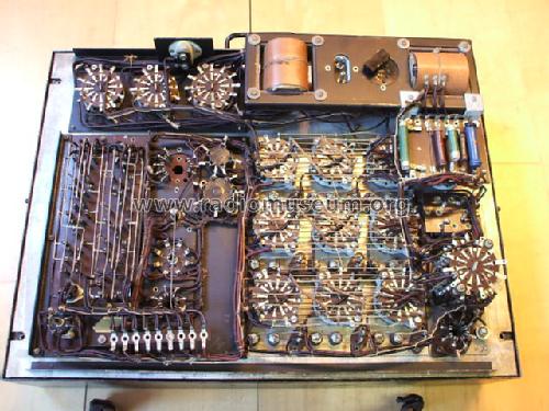
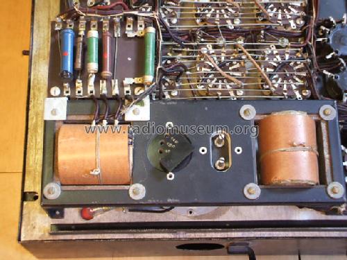
UInnenseite


Clicca sulla miniatura dello schema per richiederlo come documento gratuito.
- Gamme d'onda
- - senza
- Tensioni di funzionamento
- Alimentazione a corrente alternata (CA) / 110-240 Volt
- Altoparlante
- - - Nessuna uscita audio.
- Materiali
- Mobile di metallo
- Radiomuseum.org
- Modello: Lampemètre Serviceman Universel 752 - Radio-Contrôle; Lyon
- Forma
- Rack
- Dimensioni (LxAxP)
- 480 x 970 x 250 mm / 18.9 x 38.2 x 9.8 inch
- Peso netto
- 12 kg / 26 lb 6.9 oz (26.432 lb)
- Fonte dei dati
- - - Data from my own collection
- Autore
- Modello inviato da Albert Walenta. Utilizzare "Proponi modifica" per inviare ulteriori dati.
- Altri modelli
-
In questo link sono elencati 59 modelli, di cui 55 con immagini e 16 con schemi.
Elenco delle radio e altri apparecchi della Radio-Contrôle; Lyon
Collezioni
Il modello Lampemètre Serviceman Universel fa parte delle collezioni dei seguenti membri.
Discussioni nel forum su questo modello: Radio-Contrôle; Lyon: Lampemètre Serviceman Universel 752
Argomenti: 2 | Articoli: 4
Hallo, habe ein mir unbekanntes Röhrenprüfgerät erhalten
Habe jetzt gesehen es ist die Serviceman type 752 Lyon
Hat jemand die Gebrauchsanweisung oder etwas fur mich??
Ich habe nur das Apparat,weiter nichts
Bin mit alles zufrieden
Danke
Radiopiet
Nederland
Allegati
- serviceman 752 (113 KB)
- serviceman 752 (118 KB)
- serviceman 752 (113 KB)
Piet Scheepers, 29.Oct.06
A.H. Walenta, 57076 Siegen, Germany
Text prepared for radiomuseum.org
LAMPMÈTRE SERVICEMAN UNIVERSEL
RADIO-CONTRÔLE-Lyon 6è
Modèle 752
Overview
The evaluating of the quality of a tube is based on an AC measurement of the cathode emission current as is found in many low budget tube testers. The method usually does not allow to measure the transconductance, amplification factor or plate impedance but it is reliable to determine if a tube is good, weak or severely damaged. In this practical respect, the SERVICEMAN UNIVERSEL can be considered to be exceptionally well designed since it exhibits a number of unusual features making the apparatus particularly adapted for repair work. These features are (see schematics):
a) fine adjustment of line voltage
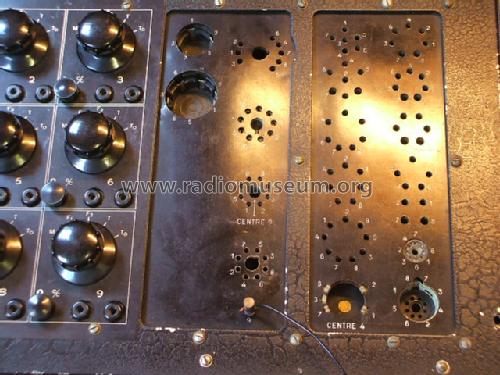
b) precision setting of heater voltage with three selectors in steps of 0.1 V, 1.0 V and 10.0 V.
c) 9 individual selectors SE1 to SE9 for each socket contact to be connected to one of the 5 test voltages:
• ground (it should be noticed that this "ground" is floating and not connected to the case which makes it useful for external oscilloscope measurements (see below),
• F1: heater. In the "measurement position this is connected to "ground"
• F2: heater voltage
• T: test voltage for tube electrodes (163 V AC). Limited to max. current by resistor.
• TD: test voltage (42 V AC) for diodes. Limited to max. current by resistor.
d) each socket contact can be interrupted by a toggle switch SC1 to SC9. Two banana plugs are connected to the ends of the switch which allows to insert a current meter in the open position or to measure the voltage with an external device. This feature is very simple but enormously useful for really finding the problems of a tube.
e) A lamp array for finding the shorted electrodes. Low voltage lamps (6.3 V, 0.1 A ) are connected in series with a resistor (2.5 kΩ) such that a current of 50 mA barely lets them glow. Any parallel resistor 30 mA) showing that the grid is working properly. Finally setting the grid on T will allow the judgement of the cathode emission in the categories bonne (good), douteuse (doubtful), mauvaise (bad).
c) Pentode and multi-grid tubes: anode on T , grids off. There should be almost no current ( 25 mA) showing that the tube basically is working properly. Setting now the grid on TD will reveal its functioning by increasing the current further. Finally setting the grid on T will allow the judgement of the cathode emission in the categories bonne (good), douteuse (doubtful), mauvaise (bad).
d) Vacuum: the banana plugs of the toggle switch for the grid are bridged with a resistor 1 M. With the grid on M shows a given current. Opening the toggle switch should not increase this current appreciably.
Text prepared for radiomuseum.org
LAMPMÈTRE SERVICEMAN UNIVERSEL
RADIO-CONTRÔLE-Lyon 6è
Modèle 752
Overview
The evaluating of the quality of a tube is based on an AC measurement of the cathode emission current as is found in many low budget tube testers. The method usually does not allow to measure the transconductance, amplification factor or plate impedance but it is reliable to determine if a tube is good, weak or severely damaged. In this practical respect, the SERVICEMAN UNIVERSEL can be considered to be exceptionally well designed since it exhibits a number of unusual features making the apparatus particularly adapted for repair work. These features are (see schematics):
a) fine adjustment of line voltage
b) precision setting of heater voltage with three selectors in steps of 0.1 V, 1.0 V and 10.0 V.
c) 9 individual selectors SE1 to SE9 for each socket contact to be connected to one of the 5 test voltages:
• ground (it should be noticed that this "ground" is floating and not connected to the case which makes it useful for external oscilloscope measurements (see below),
• F1: heater. In the "measurement position this is connected to "ground"
• F2: heater voltage
• T: test voltage for tube electrodes (163 V AC). Limited to max. current by resistor.
• TD: test voltage (42 V AC) for diodes. Limited to max. current by resistor.
d) each socket contact can be interrupted by a toggle switch SC1 to SC9. Two banana plugs are connected to the ends of the switch which allows to insert a current meter in the open position or to measure the voltage with an external device. This feature is very simple but enormously useful for really finding the problems of a tube.
e) A lamp array for finding the shorted electrodes. Low voltage lamps (6.3 V, 0.1 A ) are connected in series with a resistor (2.5 kΩ) such that a current of 50 mA barely lets them glow. Any parallel resistor 30 mA) showing that the grid is working properly. Finally setting the grid on T will allow the judgement of the cathode emission in the categories bonne (good), douteuse (doubtful), mauvaise (bad).
c) Pentode and multi-grid tubes: anode on T , grids off. There should be almost no current ( 25 mA) showing that the tube basically is working properly. Setting now the grid on TD will reveal its functioning by increasing the current further. Finally setting the grid on T will allow the judgement of the cathode emission in the categories bonne (good), douteuse (doubtful), mauvaise (bad).
d) Vacuum: the banana plugs of the toggle switch for the grid are bridged with a resistor 1 M. With the grid on M shows a given current. Opening the toggle switch should not increase this current appreciably.
Albert Walenta, 12.Jun.06