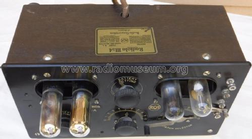
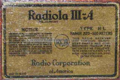
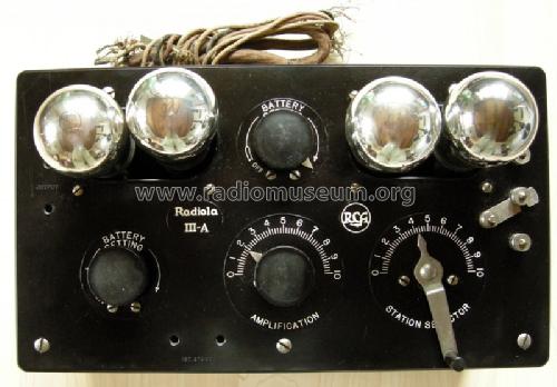
Radiola III A (3A, IIIA) AR-802 Type RL
RCA (RCA Victor Co. Inc.); New York (NY)
- Land
- USA
- Hersteller / Marke
- RCA (RCA Victor Co. Inc.); New York (NY)
- Jahr
- 1924

- Kategorie
- Rundfunkempfänger (Radio - oder Tuner nach WW2)
- Radiomuseum.org ID
- 54291
-
- anderer Name: RCA Manufacturing || Victor Talking Machine


Collection privée (réf.: 123, 355, ...)

Röhren nicht original
Tubes not original; Kaunas Lithuania
USA RCA 1924 Radiola IIIA

aus ebay, mit Erlaubnis des Verkäufers mono

aus ebay, mit Erlaubnis des Verkäufers mono
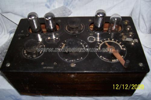


Ebay User malandpat Item 251033773545
Ebay User malandpat Item 251033773545
Ebay User malandpat Item 251033773545
Ebay User malandpat Item 251033773545
Ebay User malandpat Item 251033773545
Ebay User malandpat Item 251033773545

Ebay User malandpat Item 251033773545
Klicken Sie auf den Schaltplanausschnitt, um diesen kostenlos als Dokument anzufordern.
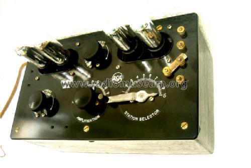
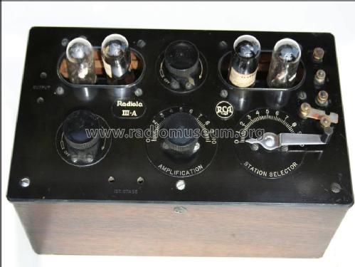
- Anzahl Röhren
- 4
- Hauptprinzip
- Geradeaus oder Audion mit Rückkopplung; 2 NF-Stufe(n)
- Anzahl Kreise
- 1 Kreis(e) AM
- Wellenbereiche
- Mittelwelle, keine anderen.
- Betriebsart / Volt
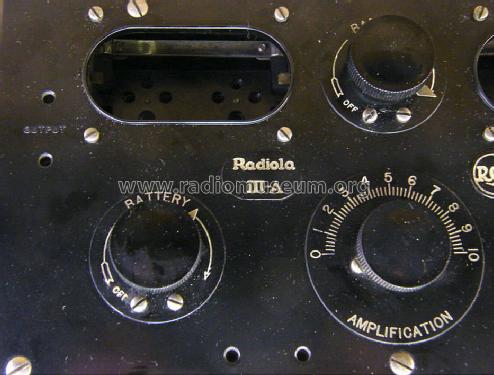
- Trockenbatterien / 1.5 & 2 x 45 & 4.5 Volt
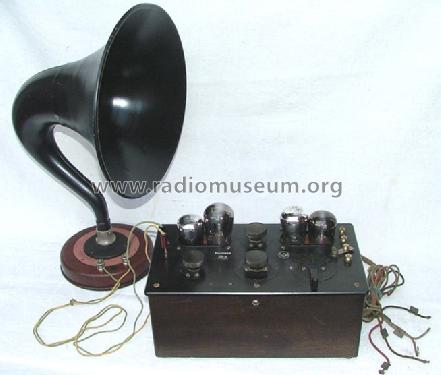
- Lautsprecher
- - Dieses Modell benötigt externe(n) Lautsprecher.
- Material
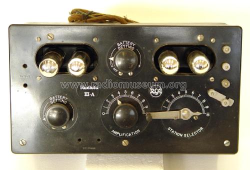
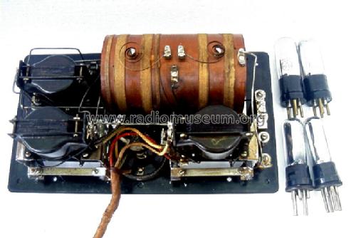
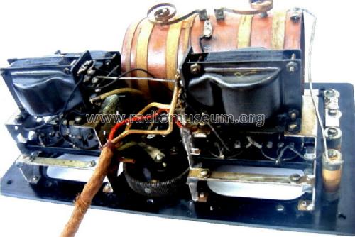
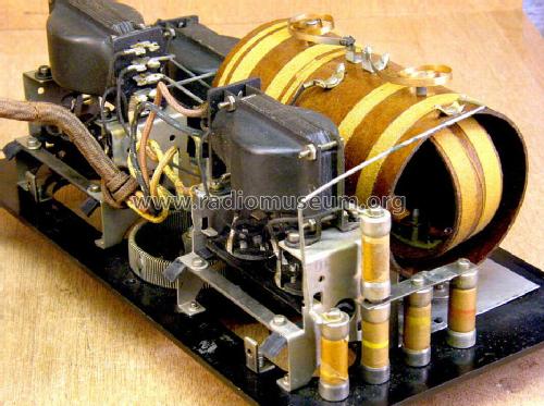
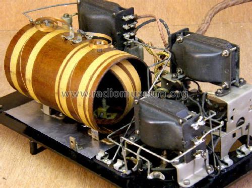
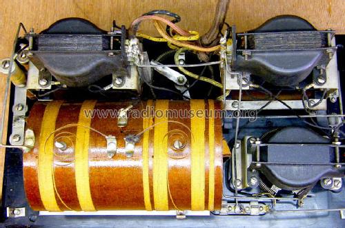
- Holz, von aussen SICHTBARE RÖHREN.
- von Radiomuseum.org
- Modell: Radiola III A AR-802 Type RL - RCA RCA Victor Co. Inc.; New
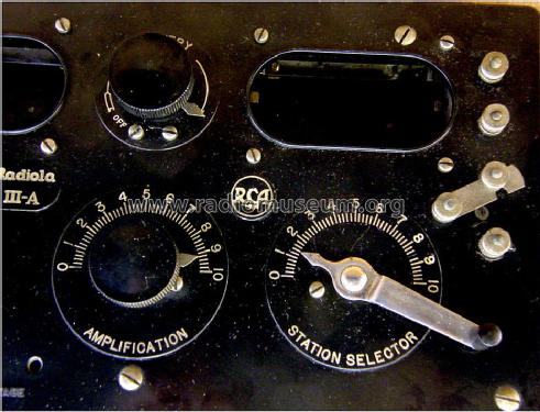
- Form
- Tischmodell, Zusatz nicht bekannt - allgemein.
- Abmessungen (BHT)
- 300 x 150 x 170 mm / 11.8 x 5.9 x 6.7 inch
- Bemerkung
-
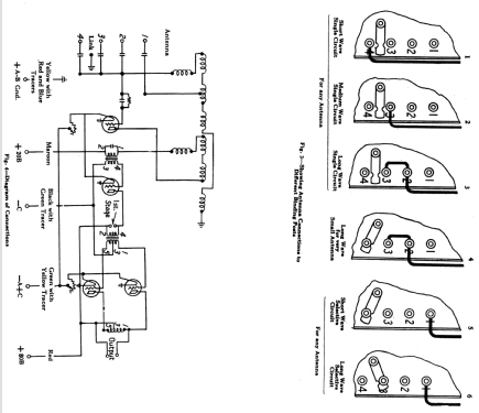
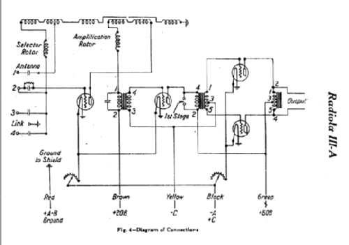
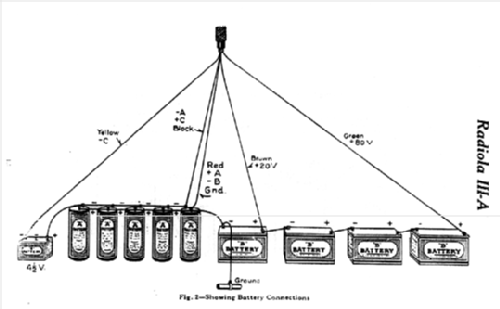
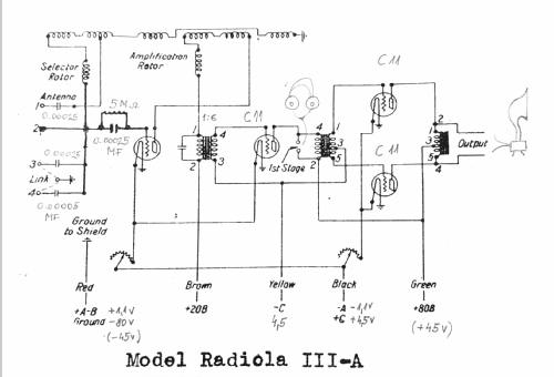
Battery setup: "A" battery for filament heating: Four or six 1.5 volt dry cells connected in parallel. Good batteries are recommended, having approximate dimensions of 2.5 inches diameter by 6 inches high. A two volt (one cell, lead type) storage battery may be used if desired.
"B" battery for supplying power to the plate circuits, consisting either of four 22.5 volt blocks connected in series. Two 45 volt plate batteries instead of four 22.5 volt blocks may be used if desired.
For "C" one 4.5 volt Negative Grid Bias Battery.
The WD11 were often replaced by UX199, using adaptors. 60 mA from 3 V made only 0.18 W per UX199, while the WD11 drew 0.25 A from a 1.5 V battery = 0.375 W, practically twice as much. The price was the same: 65 USD.Push-pull output for an external loudspeaker, connected to the "Output" pin jacks.
Note that headphones may also be used by connecting them to the pin jacks just above the "1st stage" near the front of the panel.
- Originalpreis
- 65.00 USD
- Datenherkunft extern
- Ernst Erb
- Datenherkunft
- Radio Collector`s Guide 1921-1932
- Schaltungsnachweis
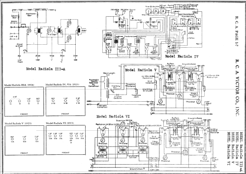
- Rider's Perpetual, Volume 1 = 1931/1934 (for 1919-1931)
- Literatur/Schema (1)
- Radio Manufacturers of the 1920's, Vol. 3 (RCA, Radiola III-A, Handbook)
- Literatur/Schema (2)
- Radio Broadcast, Mar. 1924. p. 443
- Weitere Modelle
-
Hier finden Sie 5143 Modelle, davon 3250 mit Bildern und 4180 mit Schaltbildern.
Alle gelisteten Radios usw. von RCA (RCA Victor Co. Inc.); New York (NY)
Sammlungen
Das Modell Radiola III A (3A, IIIA) AR-802 befindet sich in den Sammlungen folgender Mitglieder.
- Adam Allerhand (USA)
- Jürgen Bauch (D)
- Konrad Birkner † 12.08.2014 (D)
- Walter Brendecke (USA)
- Wayne Childress (USA)
- Otto Frosinn (D)
- Zenonas Langaitis (LT)
- Geri Meier (CH)
- Hector Ruben Menendez (RA)
- Roberto Montalto (I)
- Bruce Morgenstern (CDN)
- Musée des Radios Museum (CH)
- Günter Möckel (D)
- Rodolfo Gaston Wenceslao Nasasta (RA)
- Javier Perez Moino (E)
- Moisés Piedade (P)
- Heinz Schmidt (D)
- Lindsay Shepherd (AUS)
- Wilhelm Siepe (D)
- Philippe Viard (F)
- Albert Vonarburg (CH)
Museen
Das Modell Radiola III A (3A, IIIA) AR-802 ist in den folgenden Museen zu sehen.
Literatur
Das Modell Radiola III A (3A, IIIA) AR-802 ist in der folgenden Literatur dokumentiert.
Forumsbeiträge zum Modell: RCA RCA Victor Co.: Radiola III A AR-802 Type RL
Threads: 2 | Posts: 6
hola a todos, son nuevo miembro y mi mas reciente restauracion es una radiola IIIa
para todos los que necesiten los valores de los capacitores que seguramente hay que reemplazar y de los transformadores que pueden tener las bobinas abiertas aqui les paso los valores:
1er trasnformador: primario 890 ohms - secundario 7.5 Kohms
2do transformador: primario 890 ohms - secundario 4,5 Kohms + 4,5 kohms
3er transformador: (impedancia de salida en realidad): 900 + 1250 Ohms
Los capacitores enumerados segun bornera de radio
1: 390 pf (no es critico) acoplamiento antena
2: 390pf (no es critico) acoplamiento grilla
3: 260pf (critico para centrar la banda)
4: 74pf (critico para centrar la banda)
para hacerla funcionar con valvulas UX199
los voltajes deben diferir un poco
cable verde 140 V
cable marron 50 V
cable amarillo -6 V
pronto agregare fotos para mejorar la explicación cuando entienda mejor esta pagina.
Rodolfo Gaston Wenceslao Nasasta, 03.May.12
Will man das Gerät dauernd betreiben, ohne kostbare WD11 oder 199 (mit Adapter), bietet sich eine einfache Lösung:
KC1 sind noch erschwinglich. Eine Hülse, über den Anodenstift geschoben, AußenØ = 4,7 mm, Bohrung 3 mm, macht die Röhre genau passend. Die Glaskolben haben gerade so Platz, d.h. sie liegen aneinander an.
Die Betriebsdaten sind natürlich zu ändern:
Heizung 2V,
Audionversorgung ca 60 V (anstatt 20 V, sonst setzt die Rückkopplung nicht ein),
Versorgung NF-Stufen ca 80 V,
Gittervorspannung um -1 V.
Es gibt adaptierte 3D6. Deren Steilheit und Verstärkung ist aber bei weitem zu hoch. Das Gerät pfeift wild vor sich hin.
Andere Adptionen von z.B. DC90, DC96 oder DF91, DF92, DF904 (als Trioden) sind ebenfalls möglich, benötigen aber auch Adapter.

und hier die KC1 mit verdicktem Stift
Konrad Birkner † 12.08.2014, 26.Sep.11