Transistor Checker SC-2
Sanwa Electric Instrument Co., Ltd.; Tokyo
- Land
- Japan
- Hersteller / Marke
- Sanwa Electric Instrument Co., Ltd.; Tokyo
- Jahr
- 1964 ??
- Kategorie
- Service- oder Labor-Ausrüstung
- Radiomuseum.org ID
- 132612


Klicken Sie auf den Schaltplanausschnitt, um diesen kostenlos als Dokument anzufordern.
- Wellenbereiche
- - ohne
- Betriebsart / Volt
- Trockenbatterien / 22,5 & 4 x 1,5 Volt
- Lautsprecher
- - - Kein Ausgang für Schallwiedergabe.
- Material
- Metallausführung
- von Radiomuseum.org
- Modell: Transistor Checker SC-2 - Sanwa Electric Instrument Co.,
- Form
- Kleines Reisegerät oder «Taschengerät» < 20 cm.
- Abmessungen (BHT)
- 178 x 130 x 95 mm / 7 x 5.1 x 3.7 inch
- Bemerkung
-
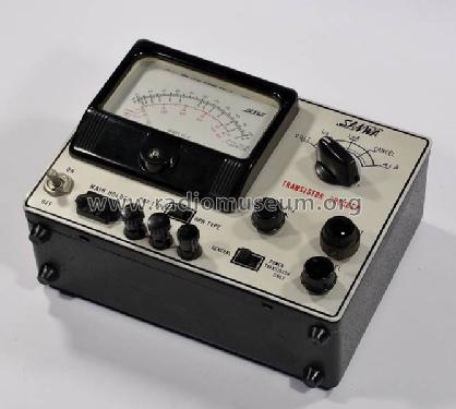
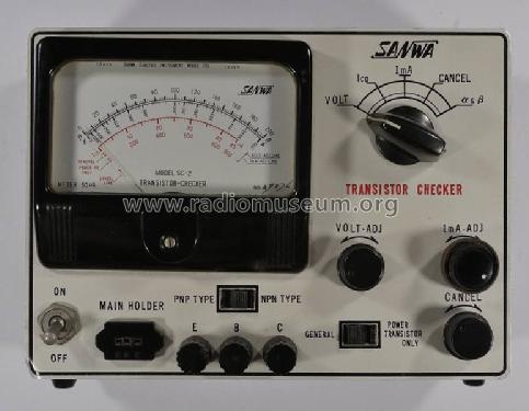
Sanwa Electric Instrument Co., Ltd.; Transistor Checker SC-2
Uses 4× 1.5 Volt and 22.5 Volt hearing aid battery. Uses a nulling principle for al measurements. Is especially useful for checking vintage transistors.
Ranges:
- β value: 0-200
- α value: 0.90-0.99
- Ico : 0-900μA & 0-45μA
- Nettogewicht
- 0.1 kg / 0 lb 3.5 oz (0.22 lb)
- Literatur/Schema (1)
- -- Original-techn. papers.
- Weitere Modelle
-
Hier finden Sie 88 Modelle, davon 79 mit Bildern und 46 mit Schaltbildern.
Alle gelisteten Radios usw. von Sanwa Electric Instrument Co., Ltd.; Tokyo
Sammlungen
Das Modell Transistor Checker befindet sich in den Sammlungen folgender Mitglieder.
Forumsbeiträge zum Modell: Sanwa Electric: Transistor Checker SC-2
Threads: 1 | Posts: 1
Dear Colleagues,
I received a request from a friend, who was experiencing difficulties with this instrument. His questions got me thinking about it - I could never understand why it read less than my more modern transistor testers.
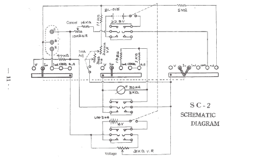
The complete circuit is now in the museum with the model, but here is an abridged version taken from the manual.

The operation of the instrument can be described as follows:-
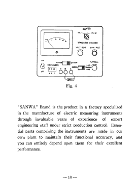
1. Insert the transistor in the socket
2. Adjust the supply voltage to 5.0 Volts with the Voltage Pot
4 (Check Ico)
5. Set the Collector current to 1mA
6. Cancel - i.e. zero the meter
7. Read the beta value
Explanation of how the circuit is intended to work (paraphrasing the manual)
(You may need to print out the circuit diagram to follow this.)
The voltage is set to 5.0 Volts - meter full scale.
The collector current is set to 1mA on the meter by altering the value of the base bias resistor formed by the 1mA adjustment potentiometer and an 11k resistor in series.
(In this switch position, the 3k meter is shunted by a 158 Ohm resistor. The meter resistance is 3k, so the combined resistance is 150 Ohms, and the voltage across the shunt will be 1 * 150 = 150 millivolts, since the meter has a 3k resistance, the current will be 150mV/3000Ohms = 50uA -so the 158 Ohm resistor is correct to turn the meter into a 1mA meter. )
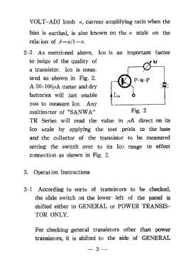
Forgetting about the Ico and Cancel steps, for the moment, we now have a steady (?) 5 Volts from the battery, and we now draw an additional 1uA from the base by switching in a 5M resistor.
So, if you don't touch the cancel button, the meter will read 1mA + the beta value. Actually, it won't because it will be off the scale.
What SANWA have done, is to use a separate circuit to cancel out the 1mA. Indeed it is so separate, it uses a 22.5 volt battery to provide an equal and opposite voltage in the collector circuit to drive the current through the meter to zero.
Having done that, the meter will read beta directly at the final step.
The Cancel circuit is simply the 22.5 volt battery, a 10k pot with a 16k resistor in series across the meter. But now, the meter has a 1k shunt (presumably to provide greater sensitivity - 200uA) - which ties in since the maximum beta value is 200 NOT 1000. Note that the CANCEL circuit will always drive the meter to the LEFT, whilst the battery can't display anything except voltage with no transistor in the socket. If the cancel circuit is powering the meter to the RIGHT with no transistor, then the battery must be the wrong way round.
Design Flaws
There are some flaws in this argument:
The first is that no account has been taken of the 1mA current drawn from the slider of the voltage setting pot. I just went through the maths, and it means that the voltage will be set to 5.0 Volts, but when 1mA is drawn - the voltage will drop to 4.58 Volts. (With a 3k pot as per the diagram). I see my instrument has a 2k pot. (As a rule-of-thumb, the pot should draw 10 x the current - 10mA. A better value would be 470 Ohms.)
The next problem is that no account has been taken of the Vbe drop - around .7 volts for some silicon transistors. This means the 5M resistor will only have about 3.9 (4.6 - .7) volts across it, not 5. You should multiply your beta by 5/3.9 For the KSP44 used for test, this would be a beta of 90, rather than 70. This is curable with a Si / Ge switch on the front panel, which would switch a silicon or germanium diode in the circuitry somewhere to compensate for the Vbe drop. (I originally thought in series with the 5M resistor, but I don't think that will work - BR)
This goes some way to explaining why on a modern component tester I get a beta of 100 for the same device.
For all that - the tester will still tell you whether the transistor is good or bad.
Perhaps the members would like to comment
Regards - Bryce
Bryce Ringwood, 05.Aug.12