World's Record Super 10
Scott Radio Labs.(E.H., Transformer); Chicago (IL)
- Land
- USA
- Hersteller / Marke
- Scott Radio Labs.(E.H., Transformer); Chicago (IL)
- Jahr
- 1927
- Kategorie
- Rundfunkempfänger (Radio - oder Tuner nach WW2)
- Radiomuseum.org ID
- 104831

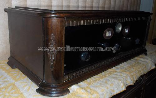
Ebay User farmerjackee Item 200880334558

Ebay User farmerjackee Item 200880334558
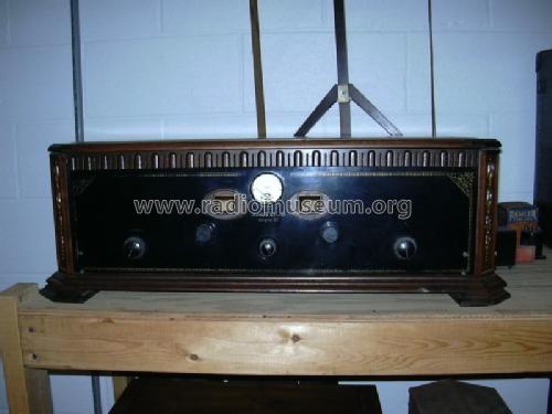
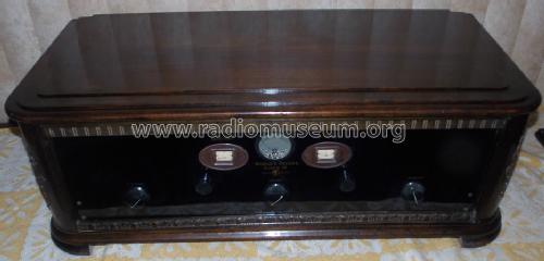
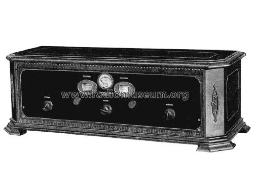
World's Record Super 10 - front view
Ebay Item number: 110951183709

Ebay Item number: 110951183709

Ebay User farmerjackee Item 200880334558
Ebay User farmerjackee Item 200880334558
Ebay User farmerjackee Item 200880334558
Ebay User farmerjackee Item 200880334558


Klicken Sie auf den Schaltplanausschnitt, um diesen kostenlos als Dokument anzufordern.
- Anzahl Röhren
- 10
- Röhren
- 201A 210_UX-Triode
- Hauptprinzip
- Super mit HF-Vorstufe
- Wellenbereiche
- Mittelwelle, keine anderen.
- Betriebsart / Volt
- Akku und/oder Batterie
- Material
- Gerät mit Holzgehäuse
- von Radiomuseum.org
- Modell: World's Record Super 10 - Scott Radio Labs.E.H.,
- Form
- Tischgerät, Truhenform, meist mit Deckel (NICHT Schrägpult).
- Abmessungen (BHT)
- 31 x 10 x 13.5 inch / 787 x 254 x 343 mm
- Nettogewicht
- 42 lb 0 oz (42 lb) / 19.068 kg
- Datenherkunft
- E.H.Scott Radio Collectors Guide (1925-1946)
- Autor
- Modellseite von Kent King angelegt. Siehe bei "Änderungsvorschlag" für weitere Mitarbeit.
- Weitere Modelle
-
Hier finden Sie 201 Modelle, davon 126 mit Bildern und 51 mit Schaltbildern.
Alle gelisteten Radios usw. von Scott Radio Labs.(E.H., Transformer); Chicago (IL)
Sammlungen
Das Modell World's Record Super befindet sich in den Sammlungen folgender Mitglieder.
Forumsbeiträge zum Modell: Scott Radio Labs.E.H: World's Record Super 10
Threads: 1 | Posts: 1
This text is on behalf of Kent King:
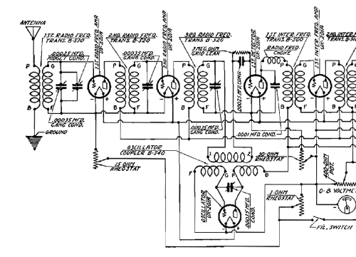
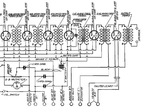
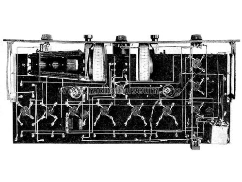
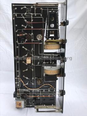
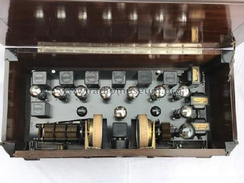
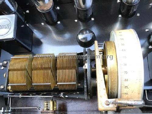
Mr. Scott introduced the World’s Record Super 10 in September 1927. The 10 shows major changes and improvements from the previous eight and nine tube sets. The greatest improvement in the World’s Record Super 10 is in the “front end”. For the first time, we see a Scott set with two stages of tuned RF. This is accomplished with the newly announced Remler “3-in-line” tuner. The tuned RF stages also eliminate the need for a loop antenna to create regeneration as in the previous design. Following the two RF stages, the signal is mixed with the oscillator output and fed into three IF stages. Following the second detector, there are two AF stages, the last being a type 210 power amp. With the additional RF stages and a 210 output, the World’s Record Super 10 developed quality sound that was unmatched by other battery receivers of the period.
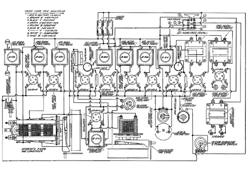
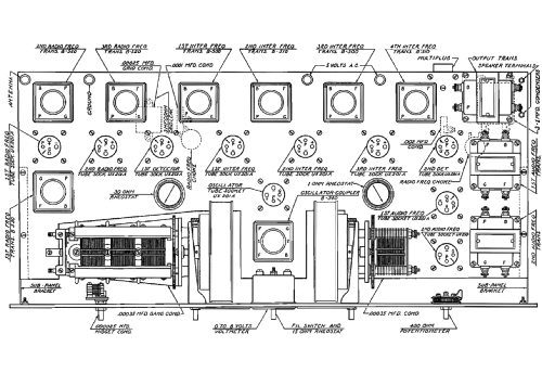
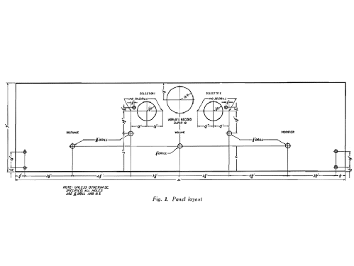
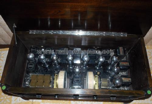
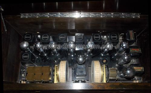
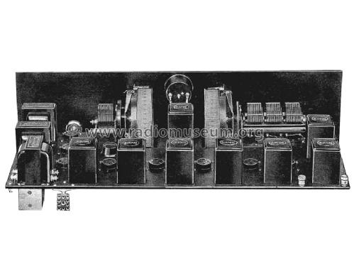
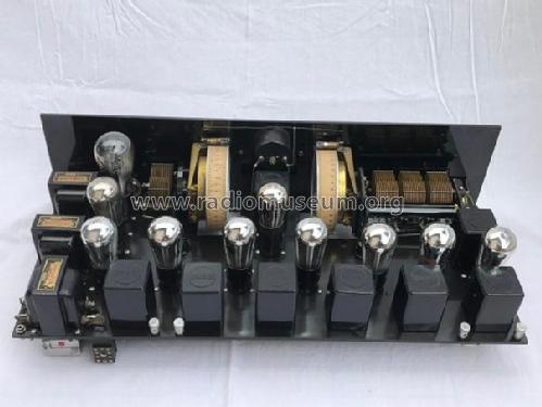
The Super 10 required eight separate Selectone transformers, all being the new “sub-panel” mounting that Scott was producing. In addition to the Selectone transformers, this set returned to Benjamin sockets, Thordarson audios, Carter rheostats and Tobe condensers.
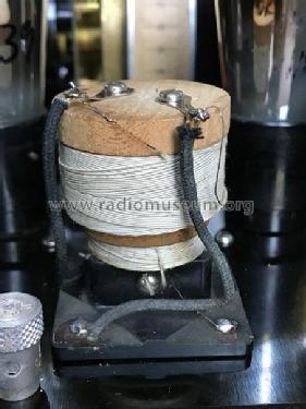
The list of sub-panel transformers required to build a World’s Record Super 10 includes all of the following: B-500 IF Transformer, B-510 Tuned Filter, B-520 RF Transformer, B-530 Antenna Coupler and a B-540 Oscillator Unit. In addition to the sub-panel transformers, Scott also offered the following baseboard mount units: R-400 or R-500 air-core and the R-410 or R-510 iron core. The oscillator coupler was also available in baseboard mounting.
Mr. Scott advertised the Super 10 heavily, running one, two and sometimes four page ads in many radio magazines. He also managed to get larger number of magazines to carry construction plans for this set. World’s Record Super 10 articles can be found in all of these publications:
Radio Listener’s Guide and Call Book, September 1927.
Citizens’ Radio Call Book, September 1927.
Radio Age, October 1927.
WCFL Radio Magazine, October 1927.
Radio News, November 1927.
Radio Listener’s Guide and Call Book, December 1927.
Citizen’s Radio Call Book, January 1928.
Radio Listener’s Guide and Call Book, March, 1928.
Radio World (series of articles), March 24, March 31 and April 7, 1928.
Although drawn in different styles, the basic circuit remained the same. Each magazine had some gimmick or modification to the basic set however. The article in Radio Listener’s Guide and Callbook, September 1927, shows a 171A output tube, rather than the type 210. In the December issue, Radio Listener’s Guide and Callbook provided plans for a “Light-Socket Operated World’s Record Super 10”. This set was quite unusual, using Sovereign AC tubes manufactured by Sovereign Electric & Manufacturing Company of Chicago. Plans for a complete B eliminator, which also provided filament voltage for the Sovereign tubes (and a type 210 output tube) were given. The Sovereign tubes used a cold cathode, so the diagram is somewhat different from the typical Super 10 schematic. The January 1928 Citizen’s Radio Callbook article described how to add a phonograph pickup to the audio section of the set. To boost the AF stages slightly, this article used a 112 tube as the first audio. The 1928 articles mention a Thordarson A/B power supply, using two 281 rectifier tubes. This supply also provided filament potential for the 210 output tube. The Radio World articles are of particular interest, since E. H. Scott authored them.
Konrad Birkner † 12.08.2014, 01.Sep.06