Shield Grid 9 SG9
Scott Radio Labs.(E.H., Transformer); Chicago (IL)
- Produttore / Marca
- Scott Radio Labs.(E.H., Transformer); Chicago (IL)
- Anno
- 1928
- Categoria
- Radio (o sintonizzatore del dopoguerra WW2)
- Radiomuseum.org ID
- 55385


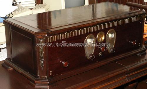
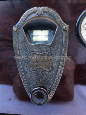
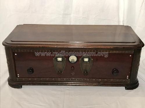
Scott SG9 in table cabinet

Scott SG9
Scott SG9
Scott SG9

Scott SG9

Scott SG9

Scott SG9 in table cabinet

Scott Shield Grid 9 with SW coils


Clicca sulla miniatura dello schema per richiederlo come documento gratuito.
- Numero di tubi
- 11
- Principio generale
- Supereterodina con stadio RF; A valvole con griglia schermo (solo se 1926-1935)
- N. di circuiti accordati
- 7 Circuiti Mod. Amp. (AM)
- Gamme d'onda
- Onde medie (OM) e 2 gamme di onde corte (2 x OC).
- Tensioni di funzionamento
- Alimentazione a corrente alternata (CA) / 110 Volt
- Altoparlante
- - Questo apparecchio richiede altoparlante/i esterno/i.
- Materiali
- Mobile in legno
- Radiomuseum.org
- Modello: Shield Grid 9 SG9 - Scott Radio Labs.E.H.,
- Forma
- Soprammobile a cassapanca o cassetta, solitamente con coperchio (NON a leggio)
- Fonte esterna dei dati
- Ernst Erb
- Riferimenti schemi
- Rider's Perpetual, Volume 1 = 1931/1934 (for 1919-1931)
- Bibliografia
- E.H.Scott Radio Collectors Guide (1925-1946)
- Altri modelli
-
In questo link sono elencati 201 modelli, di cui 126 con immagini e 51 con schemi.
Elenco delle radio e altri apparecchi della Scott Radio Labs.(E.H., Transformer); Chicago (IL)
Collezioni
Il modello Shield Grid 9 fa parte delle collezioni dei seguenti membri.
Discussioni nel forum su questo modello: Scott Radio Labs.E.H: Shield Grid 9 SG9
Argomenti: 1 | Articoli: 1
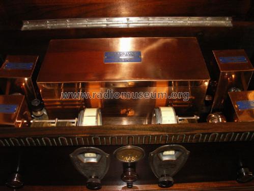
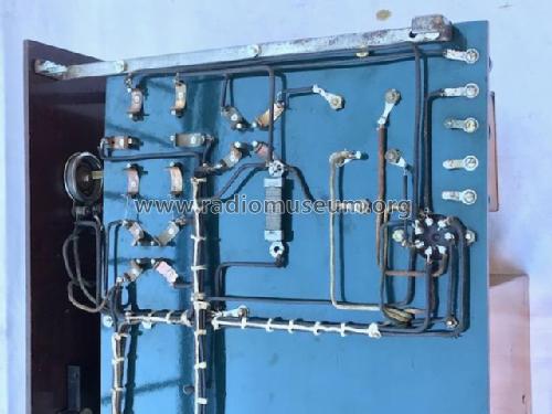
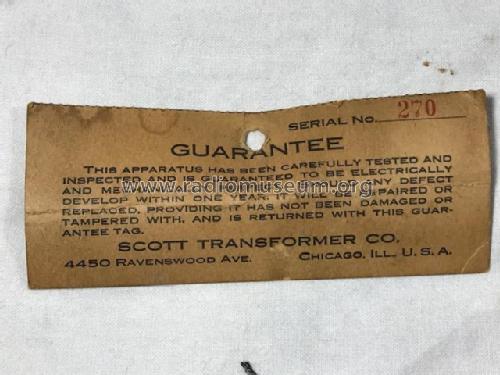
In the August 1928 issue of Radio News, the full page Scott ad introduces the Shield Grid 9. The ad also mentioned the availability of a new power supply amplifier, using a type 250 output tube. The first full description of the Shield Grid 9, and a wiring diagram, appear in the September 1928, issue of the Citizen’s Radio Callbook. The Shield Grid has only a single RF stage, with a small amount of regenerative signal returned from the first detector. The set actually has only eight tubes on the chassis: RF (201A), oscillator (201A), first detector (240), three IF stages (222), the second detector (201A) and an audio stage (112A). The ninth tube is the type 250 final audio on the power supply unit. Scott did not count the rectifier tubes at this time (two type 281 half-wave rectifiers). For the kit builder, the IF unit came as a single, factory sealed installation. The wiring of the set was therefore greatly simplified, and IF alignment problems were eliminated. It is quite likely that a competent kit builder could meet Scott’s claim of four hours to build.
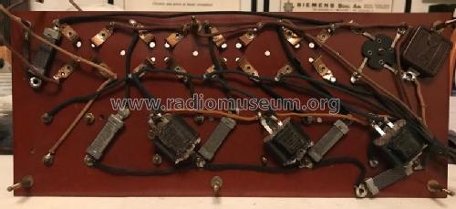
Scott continued to promote the Shield Grid 9 with construction articles in several radio magazines. Radio Listener’s Guide and Callbook had articles on the Shield Grid 9 in both their September and November issues. Scott also ran another article in the November 1928 issue of Citizen’s Radio Callbook. This article introduced a slightly different version, called the Shield Grid 9B. Apparently, many of Scott’s customers were still without a source of AC power in their homes. The 9B is a fully battery operated version of the Shield Grid 9, with nine tubes on the tuner chassis. Scott’s 9B is almost identical to the original 9, but the audio transformer (Scott designation #640) is replaced with a “double audio transformer”, designation #641. (The article mistakenly refers to this as the #645 unit, but the parts list and known sets all contain a #641 transformer.) Early samples of the #641 transformer are in a wider than normal, black transformer casing. Later sets have the #641 transformer in a matching copper can. A final audio stage using a 171A output tube is wedged onto the chassis. With this arrangement, full loudspeaker volume is available without the use of the power supply/amplifier unit.
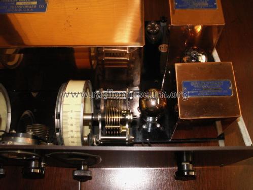
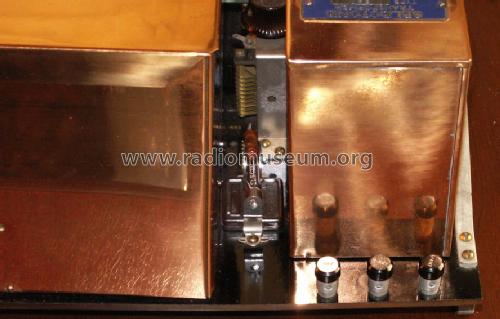
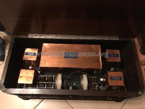
In each of these articles, we see Scott’s earliest attempt to capture a new market: the Shield Grid 9 receiver is able to operate not only in the broadcast band (200-550m), but also in several short-wave (SW) bands. Three of the square copper cans are actually plug in coils (the can at the right rear of the chassis is the unmoving audio transformer). Interestingly, each article seems to mention a different availability for the SW bands. The Citizen’s Radio Callbook November article states that coils are available for the 20-50m and 35-90m ranges (about 6 to 15 MHz and 3 to 8 MHz respectively). The Radio Listener’s Guide and Call book article mentions coils for 80, 40 and 20 meters. A W. C. Braun radio parts catalog shows coils for 70-210m and 30-75m. (About 1.5 to 4 MHz and 4 to 10 MHz.) Very few SW coils are known to exist today. One existing set, marked as noted in the W. C. Braun catalog, test very closely to the ranges specified in the catalog. Scott claimed that the Shield Grid 9 was the first truly “All-wave” radio offered to the radio public.
Kent King, 02.Sep.06