Elektronika - Электроника 68
Semiconductor Device Plant; Yoshkar-Ola
- Land
- Soviet Union (UdSSR)
- Hersteller / Marke
- Semiconductor Device Plant; Yoshkar-Ola
- Jahr
- 1968–1974
- Kategorie
- Diverses (Sonstiges) - siehe Bemerkungen
- Radiomuseum.org ID
- 318056


Klicken Sie auf den Schaltplanausschnitt, um diesen kostenlos als Dokument anzufordern.
- Anzahl Röhren
- 14
- Röhren
- ИН-8-2 ИН-8-2 ИН-8-2 ИН-8-2 ИН-8-2 ИН-8-2 ИН-8-2 ИН-8-2 ИН-8-2 ИН-8-2 ИН-8-2 ИН-8-2 ИН-8-2 ИН-8-2
- Anzahl Transistoren
- 659
- Halbleiter
- Wellenbereiche
- - ohne
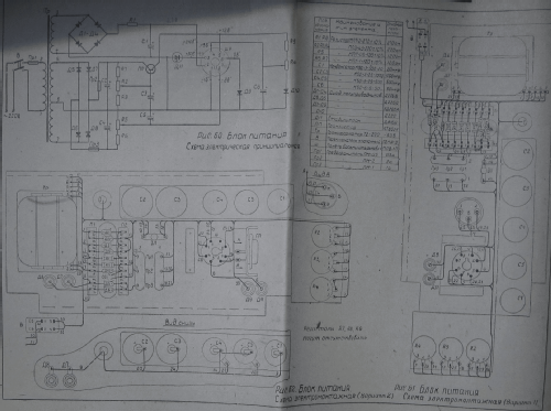
- Betriebsart / Volt
- Wechselstromspeisung / 220 Volt
- Lautsprecher
- - - Kein Ausgang für Schallwiedergabe.
- Material
- Plastikgehäuse (nicht Bakelit), Thermoplast
- von Radiomuseum.org
- Modell: Elektronika - Электроника 68 - Semiconductor Device Plant;
- Form
- Tischgerät, Schräg-Pult-Form.
- Abmessungen (BHT)
- 410 x 210 x 480 mm / 16.1 x 8.3 x 18.9 inch
- Bemerkung
-
identical to:
- Электроника ДД
- Электроника Б3-01
- Sharp Compet CS-30A
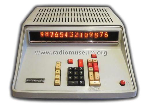
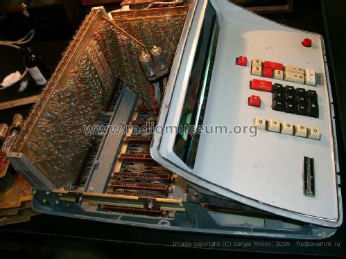
This stationary or desktop calculator, manufactured in the Soviet Union in the years 1968, is a practically identical clone, except for 2 or 3 transistors and a pair of diodes, to the Sharp Compet CS-30A calculator of the year 1967.
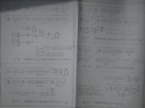
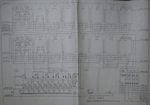
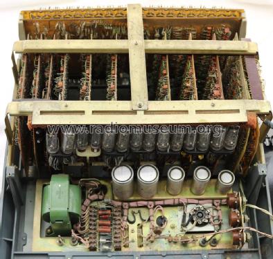
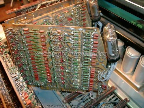
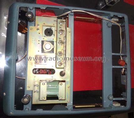
With totally discrete technology; this masterpiece of digital electronic engineering, uses diodes and transistors to perform logical operations. The technology used is DTL (Diode Transistor Logic) prior to TTL, has no integrated circuit (IC) inside.
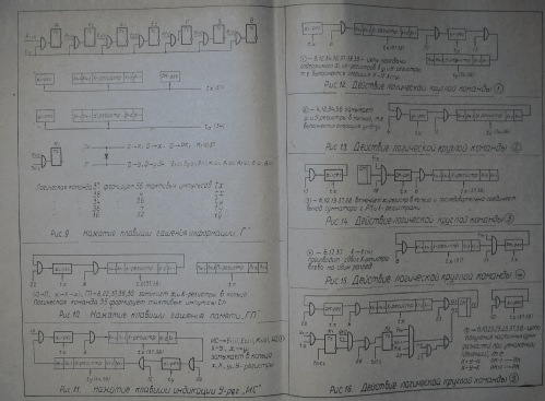
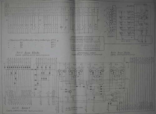
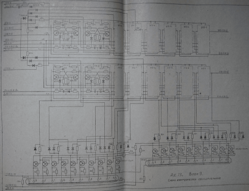
The decimal numbers entered by the keyboard are converted to binary on board No. 1, which contains a FLIPS FLOPS that prevent the activation of 2 keys at once or a key and a function.
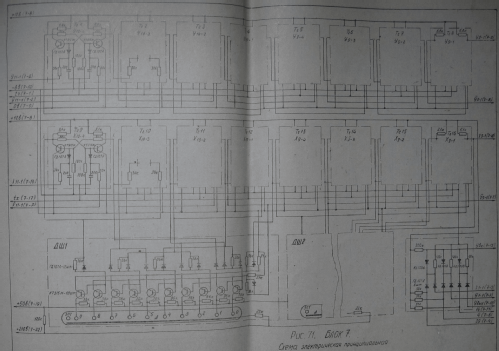
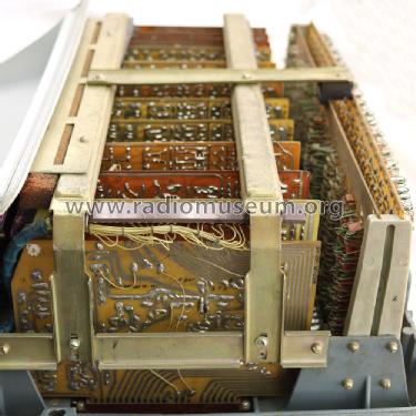
The numbers already converted to binary code are entered in the memory register of the less significant digit (Board Nº 3). The memory registers are fully constructed by flips flops with the connections of CLOCK inputs or triggers through capacitors. These registers are connected in series. The registers are located next to the binary to decimal decoder and the nixie excitation circuits on board Nº 3, 4, 5, 6, 7, 8, 9 and the memory register is located on board Nº 14. The numerical representation screen is made up of NIXIES valves and the BINARY-DECIMAL decoder circuit is directly connected to the memory registers, so that data changes can be observed while the machine is operating.
The frequency of the master CLOCK is situated in the order of 40 kHz, and for educational and practical purposes this frequency can be lowered as much as 1Hz even stopping at a certain time and resuming at ease without suffering alterations in calculation. Working in original regime, the machine performs addition and subtraction operations in 0.2 seconds and multiplications and divisions are performed in 1.4 seconds at most. The clock frequency is divided in 2 several times and recomposed in different ways to form complex wave trains destined to count in serial form in data passage through the memory registers. These circuits are found on board Nº 12.
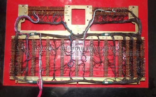
This machine was one of the first to have COMMANDS in its hardware, board Nº 13 and a board containing in hardware format the program to perform certain calculations.
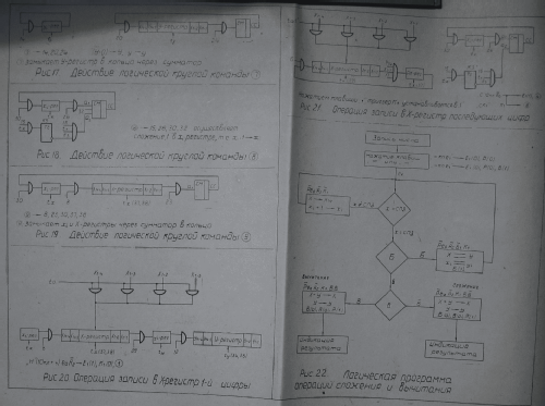
The program board could be changed so that the machine could perform other mathematical operations. The commands activate or deactivate logic gates that alter the course of the data in the memory registers, some commands even alter pulse trains formed by the master CLOCK oscillator which alters the passage of serial data through the memory registers. Specialized flips flops generate the directives that conclude in commands when these are activated by means of algebraic functions of the main keyboard. An array of diodes (logic gates interconnected with each other) links the commands to FLIPS FLOPS, Memory Registers and other commands. Some commands perform simple operations and others work in a loop.It is capable of detecting overflow errors and the associated circuits were on board Nº 10.
Negative calculations cannot be performed and there is no floating point calculation capability, the machine has on its keyboard the options of 0, 2, 4, 6 decimals and rounding. The memory registers of the decimal points are located on board Nº 11.
The calculations are simplified in a logical way, in an addition, or inverse addition (subtraction); repetitive addition (multiplication) and repetitive inverse addition (division). Therefore, only one serial adder is needed, with carry. The adder is built by 4 flips flops and a gate that makes the logical addition of data obtained from the memory registers in a serial way and by the commands, the carrying is in charge of the 4 flips flops. These circuits and associated are contained in the board Nº2.
- Nettogewicht
- 13.5 kg / 29 lb 11.8 oz (29.736 lb)
- Literatur/Schema (1)
- -- Original-techn. papers. (Arkhipov n . H . - Diseño y mantenimiento de la máquina " Electronics-DD "; [ Proc . manual para la)
- Autor
- Modellseite von Rodolfo Gaston Wenceslao Nasasta angelegt. Siehe bei "Änderungsvorschlag" für weitere Mitarbeit.
- Weitere Modelle
-
Hier finden Sie 1 Modelle, davon 1 mit Bildern und 1 mit Schaltbildern.
Alle gelisteten Radios usw. von Semiconductor Device Plant; Yoshkar-Ola
Sammlungen
Das Modell Elektronika - Электроника 68 befindet sich in den Sammlungen folgender Mitglieder.