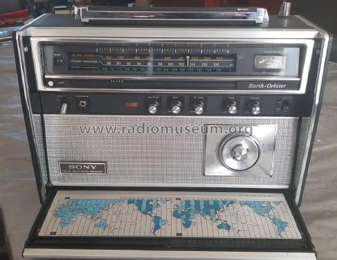
Earth-Orbiter CRF-5090
Sony Corporation; Tokyo
- Paese
- Giappone
- Produttore / Marca
- Sony Corporation; Tokyo
- Anno
- 1972 ?
- Categoria
- Radio (o sintonizzatore del dopoguerra WW2)
- Radiomuseum.org ID
- 111091


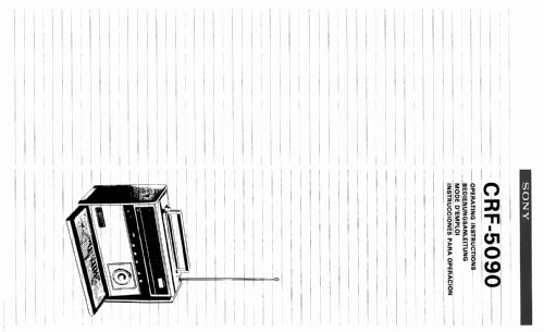

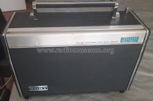


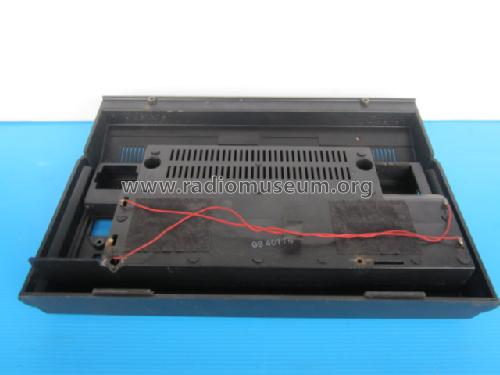
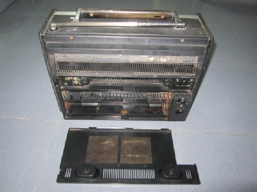
Gerät mit geschlossener Abdeckung

Clicca sulla miniatura dello schema per richiederlo come documento gratuito.
- Numero di transistor
- 20
- Semiconduttori
- Principio generale
- Supereterodina (in generale); ZF/IF 455/10700 kHz
- Gamme d'onda
- Onde medie (OM), lunghe (OL), piú di 2 gamme di onde corte (> 2 x OC) e MF (FM).
- Tensioni di funzionamento
- Rete / Batterie (ogni tipo) / 100; 120; 220; 240 / D: 8 x 1.5 Volt
- Altoparlante
- AP magnetodinamico (magnete permanente e bobina mobile) / Ø 5 inch = 12.7 cm
- Materiali
- Vari materiali
- Radiomuseum.org
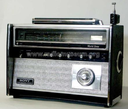
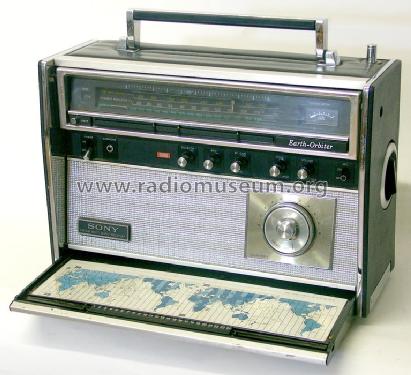
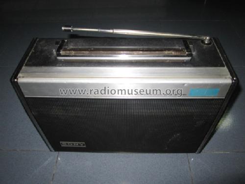
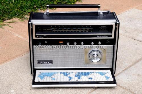
- Modello: Earth-Orbiter CRF-5090 - Sony Corporation; Tokyo
- Forma
- Apparecchio portatile > 20 cm (senza la necessità di una rete)
- Dimensioni (LxAxP)
- 345 x 275 x 130 mm / 13.6 x 10.8 x 5.1 inch
- Annotazioni
-
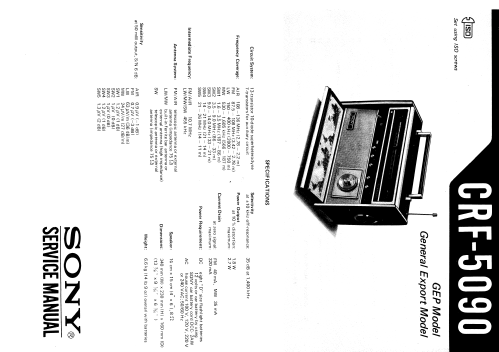
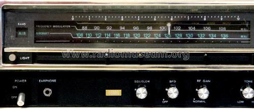
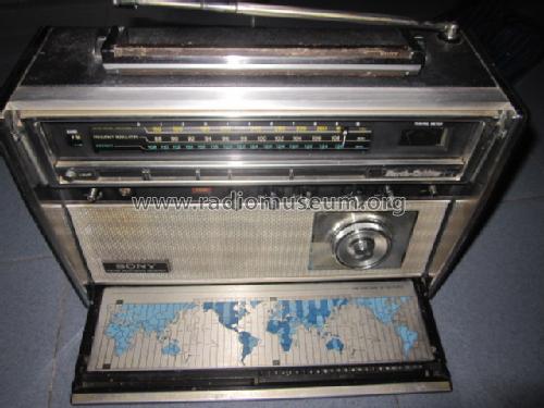
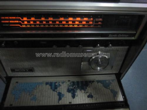
Sony model Earth-Orbiter CRF-5090
Wave bands:
- VHF Airband: 108-136 MHz,
- LW
- MW
- SW bands:
- SW1 1,6-3,5 MHz
- SW2 3,5-9 MHz
- SW3 9-14 MHz
- SW4 14-21 MHz
- SW5 21-26 MHz
Equipped with BFO and Squelch.
Very similar to CRF-5080 but with AIR band coverage and FM Squelch.Material plastic, iron and aluminium.
- Peso netto
- 4.7 kg / 10 lb 5.6 oz (10.352 lb)
- Bibliografia
- Antique Radio Magazine - Italy, Club Antique Radio Magazine (n. 105, jan-feb 2012)
- Autore
- Modello inviato da un iscritto da A. Utilizzare "Proponi modifica" per inviare ulteriori dati.
- Altri modelli
-
In questo link sono elencati 4077 modelli, di cui 3934 con immagini e 977 con schemi.
Elenco delle radio e altri apparecchi della Sony Corporation; Tokyo
Collezioni
Il modello Earth-Orbiter fa parte delle collezioni dei seguenti membri.
Discussioni nel forum su questo modello: Sony Corporation;: Earth-Orbiter CRF-5090
Argomenti: 3 | Articoli: 3
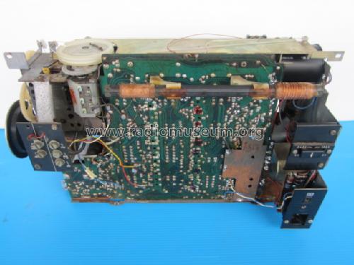
I have just completed a repair to one of these receivers, but it is worth noting that the service information presented here and elsewhere did not bear any relation to the layout of the receiver, either internally (printed circuit board) or in terms of actual circuitry.
It seems that later models use the printed circuit board from the model CRF-5100, as my example did, but retain the same waveband coverage as the CRF-5090.
I hope this helps any fellow collectors who may encounter curiosities with this model.
Mike Izycky, 09.Feb.20
Repair of warped dial scale - Sony CRF-5090
© Martin Cook 15th August 2010
Apparently this is quite a common problem with this series of receivers. This one was bought on a
local auction site where it was clearly advertised as having the problem which probably explains the
low purchase price.
After initial inspection, a good clean inside and out, switches and potentiometers lubricated and a
check of the alignment with only slight adjustment required, it was decided that the radio was in
good enough condition to warrant a repair of the scale.
The scale appeared to be “flattened” only on one side. The previous owner said that he used the
receiver only on the aircraft band and that it was always used with mains power. With the aircraft
band selected, the “flat” section was uppermost. When run on mains power, the scale lamps are
always illuminated, so perhaps the scale is softened by the lamp heat.
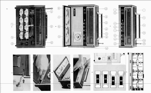
Figure 1 - the scale before removal.
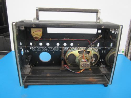
The scale can be removed quite easily after unsoldering the dial lamp leads from their tagstrip.
Loosening the screws on the right hand end shaft coupler allows the coupler to be slid down the
shaft. There is now sufficient space to lift the shaft out with the dial. The left hand end just sits in a
hole in the mounting plate.
The scale is attached to the two drum ends by two self tapping screws, a melted plastic “rivet” and
some double-sided tape. A small hole was drilled through the plastic “rivet’ with a drill held in a pin
chuck - the excess plastic was chipped away with a scalpel blade. The two self-tapping screws were
removed. The double-sided tape had gone quite brittle and was carefully sliced through, again with a
scalpel blade. With the scale removed, the remaining dried out glue was softened and washed away
from the drum ends and the back of the scale. It was found that the scale was not affected by water,
but solvents were avoided.
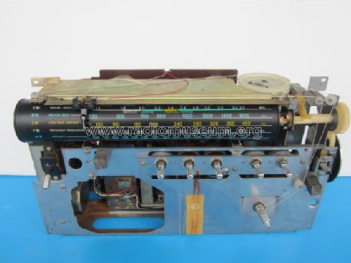
Fig 2 - Scale removed.
The scale was gently flattened and then scanned at 600dpi in case of accidents!
Fig 3. Scanned scale:
The scale was then placed on a flat piece of 9 ply wood between two sheets of greaseproof paper.
Then with an ordinary flat iron starting on the lowest heat setting, the heat was slowly increased until
the plastic softened then let it cool. Results were quite good with very little distortion apart from a
slight “barrel” effect. However, on closer inspection it was found that the whole scale had shrunk
slightly. By measuring the drum ends and comparing with the earlier scanning, it was found that the
scale had shrunk by about 3mm in both dimensions. The now flat scale was scanned again and then
enlarged by 2% - the calculated amount required to bring it back to full size. A paper print was
made, trial fitted and found to be accurate.
A local printshop was found that did one-off photocopying. They showed me a few sheets of thin
white plastic of varying thicknesses and one was selected that was about the same thickness as the
original scale. They then produced two accurately sized copies (one for insurance!) within a few
hours. The colours were now not quite as vivid or intense but it was close and the size was exactly
right. The copies were laser printed not inkjet so the colour is bonded into the surface.
The original dial lamps were removed and replaced with back to back LEDs across the 6volt AC
transformer winding. However this was unsatisfactory as the LED's are driven from 12vDC when on
batteries. The LEDs were then wired in series with a diode backwards across them with a 100ohm
dropper resistor. Across 6volts they passed about 50mA for each half-cycle and there is another
dropper for running from 12vDC. The tops of the rounded LEDs were filed to a wedge shape to
elongate the light pattern to cover the dial.
The edges of the scale were cut with a craft knife and straight edge, and made the holes square with
a scalpel. (I would have liked to use a leather punch but don't own one and a paper hole punch is too
big.) The holes in the drum where the plastic rivets were drilled out were tapped to fit small screws.
Fig 4. Scale drum end.
The inner end of the scale was fitted to the drums and attached loosely with (now) two screws and
then fed the scale around and held in place with elastic bands. The other two screws were then fitted
loosely too. The grommets holding the LED’s were fitted over the ends of the scale and everything
adjusted for best fit. The centre flaps were then glued down to each other with contact adhesive and
allowed to dry. Using adhesive applied with a screwdriver blade, glued down the rest of the flaps to
each other. Pressure was applied with more elastic bands. The small tabs were bent over.
Fig 5. Scale glued.
The ends flaps were then adjusted for best fit and the four screws gently tightened. As the new scale
is slightly thicker than the original, it was decided that gluing of the scale to the drum ends was
unnecessary.
Fig 6. Finished scale.
The scale was then refitted into the radio and the LED’s connected. A trial run of lamp brilliance was
satisfactory with the scale lightly but evenly illuminated on mains power and with adequate brilliance
when the “Light” button is pushed. A check of the scale calibration showed that no adjustment was
required. The chassis was then fitted back into the case and now looks really good.
Fig 7 Complete.
© Martin Cook 15th August 2010
Martin Bösch, 14.Nov.10
Hi guys,
I have successfully repaired the warped dial scale on my CRF5090 which I believe is a common fault on these models. I have written up how the repair was carried out with photos.
Thanks and best regards - Martin
Allegati
- Scale Repair (Text and Pictures)) (561 KB)
Martin Cook, 12.Aug.10