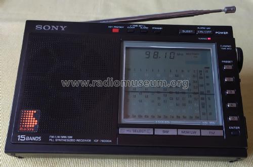
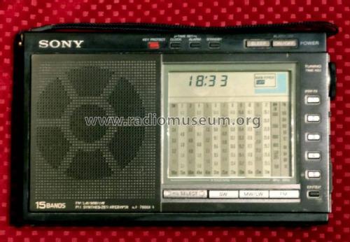
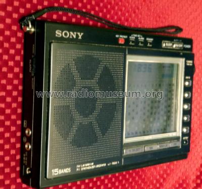
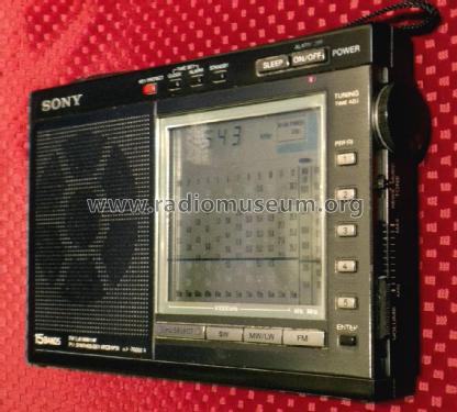
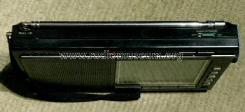
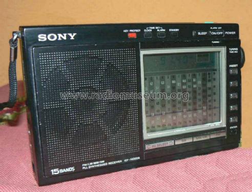
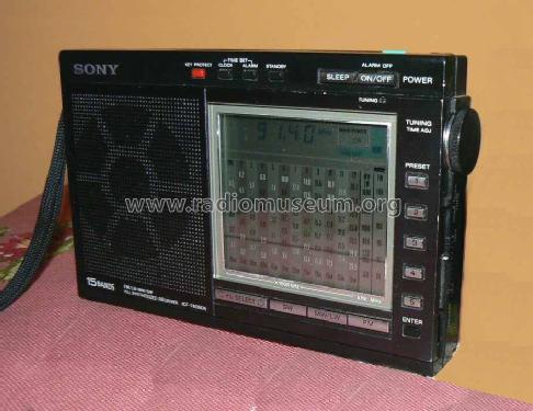
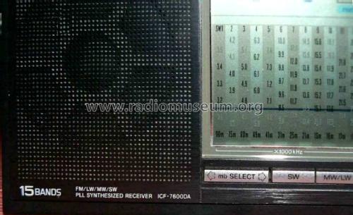
FM/LW/MW/SW PLL Synthesized Receiver ICF-7600DA
Sony Corporation; Tokyo
- Country
- Japan
- Manufacturer / Brand
- Sony Corporation; Tokyo
- Year
- 1987
- Category
- Broadcast Receiver - or past WW2 Tuner
- Radiomuseum.org ID
- 74869


Click on the schematic thumbnail to request the schematic as a free document.
- Number of Transistors
- Semiconductors present.
- Semiconductors
- Main principle
- Superhet, double/triple conversion
- Wave bands
- Broadcast, Long Wave, more than 2 x SW plus FM or UHF.
- Power type and voltage
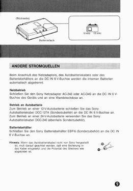
- Batteries / addl. power jack / AA: 4 x 1,5 / 6 Volt
- Loudspeaker
- Permanent Magnet Dynamic (PDyn) Loudspeaker (moving coil) / Ø 7.7 cm = 3 inch
- Power out
- 0.4 W (undistorted)
- Material
- Plastics (no bakelite or catalin)
- from Radiomuseum.org
- Model: FM/LW/MW/SW PLL Synthesized Receiver ICF-7600DA - Sony Corporation; Tokyo
- Shape
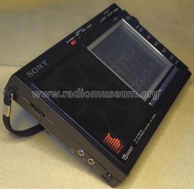
- Very small Portable or Pocket-Set (Handheld) < 8 inch.
- Dimensions (WHD)
- 192 x 117 x 32 mm / 7.6 x 4.6 x 1.3 inch
- Notes
-
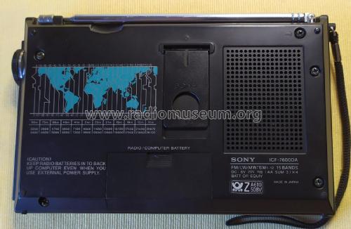
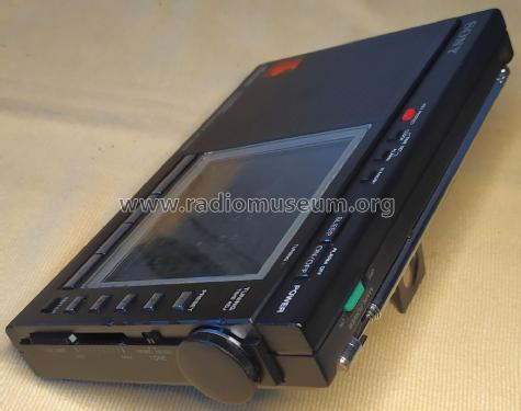
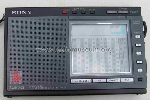
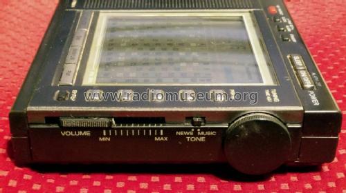
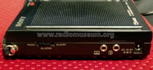
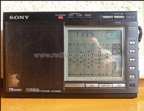
The Sony ICF-7600DA FM/LW/MW/SW PLL Synthesized Receiver features an LCD with digital and pseudo analog readout, 15 station presets, clock, alarm, sleep timer, earphone jack, an external power jack, and Recording Output jack (0.775 mV / -60 dB / 1 KOhm impedance).
This is a broadcast receiver for public radio stations and therefore SSB/BFO is not needed.
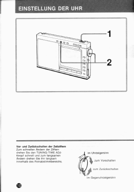
As the radio emulates an analog classical radio, the only tuning system available is the band selector and the rotary tuning knob.
The radio has 15 memory presets and additionally it remembers the last tuned radio station on FM, MW/LW, and SW. These memories are not persistent, requiring less than 1 minute without power when replacing the batteries (this is a design choice, as the UPD1715G-529 Management Control Unit processor was not configured with an additional persistent memory device).
Frequency bands
- FM (Mono):
- 76.0 - 108.0 MHz for US, CAN models
- 87.5 - 108.0 MHz for AEP, UK, E, AUS models
- 50 kHz channel stepping
- LW:
- 150 - 285 kHz
- 3 kHz channel stepping
- MW:
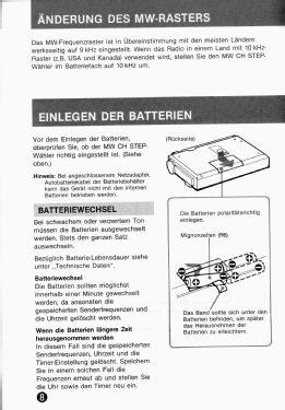
- 9 / 10 kHz stepping selectable at the switch inside the battery compartment
- 531 - 1602 kHz
- 3 kHz channel stepping (9 kHz selection)
- 530 - 1700 kHz
- 5 kHz channel stepping (10 kHz selection)
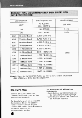
- SW 1-12 broadcast bands
- 3025 - 26100 kHz with no continuous coverage
- SW1: 90 m (3025 - 3565 kHz)
- SW2: 75 m (3700 - 4215 kHz)
- SW3: 60 m (46650 - 5165 kHz)
- SW4: 49 m (5800 - 6315 kHz)
- SW5: 41 m (6950 - 7465 kHz)
- SW6: 31 m (9375 - 10010 kHz)
- SW7: 25 m (11525 - 12160 kHz
- SW8: 21 m (13375 - 14010 kHz)
- SW9: 19 m (14975 - 15610 kHz)
- SW10: 16 m (17475 - 18110 kHz)
- SW11: 13 m (21325 - 21960 kHz)
- SW12: 11 m (25475 - 26100 kHz)
- 5 kHz channel stepping
This model is identical to US model ICF-7700).
- FM (Mono):
- Net weight (2.2 lb = 1 kg)
- 0.6 kg / 1 lb 5.1 oz (1.322 lb)
- External source of data
- R.Lichte
- Mentioned in
- - - Manufacturers Literature
- Author
- Model page created by Martin Bösch. See "Data change" for further contributors.
- Other Models
-
Here you find 4076 models, 3933 with images and 977 with schematics for wireless sets etc. In French: TSF for Télégraphie sans fil.
All listed radios etc. from Sony Corporation; Tokyo
Collections
The model FM/LW/MW/SW PLL Synthesized Receiver is part of the collections of the following members.
Forum contributions about this model: Sony Corporation;: FM/LW/MW/SW PLL Synthesized Receiver ICF-7600DA
Threads: 2 | Posts: 2
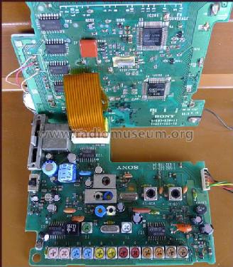
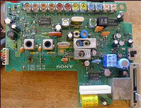
Sony equipment of that era was afflicted with the infamous SMD aluminum round can type electrolytic capacitors. They are well known to fail by leaking the electrolyte attacking the components and copper traces around before going dry and dead.
The later revisions of these model use two or four of these caps that usually need to be replaced.
That was the case with my unit where the 47uF cap have leaked. I decided to replace all four capacitors.
The radio was working before the repair, but I noticed an improvement in the sound quality after installing new capacitors.

Jose Mesquita, 23.Jul.22
Model revisions
Production started in 1987 and at least three revisions of this model were made during its short production life (production allegeded stopped in 1989):
- Up to Serial Number 7901 - This is the original design.
- From Serial Number 7902 to 62626 - New improved ACG circuit, adding IC7 and removing some of the original AGC components (see Service Manual).
- From Serial Number 62627 to "X" - In 1988.1, the Receiver PCB was changed, namely to replace two electrolytic caps marked as C20 and C83 on the Conductor Side, with SMD round can types installed on the Component Side (see Service Manual Supplement 1)
- Also, the Italian version was added to the existing US, CAN, E, AEP, UK, FR, and AUS versions.
- From Serial Number "X" to "Y" - Somewhere in 1988 or 1989, another PCB revision was done, where two more capacitors were replaced with those SMD aluminum round can types.
- My unit with s/n 104566 have these two additional 10uF 16V SMD round can type electrolytic capacitors installed on the Component Side replacing the original ones installed at the Conductor Side at positions C74 and C76
- With this revision, a total of four SMD aluminum round can electrolytic cap types are seen on the Component Side of the Receiver PCB.
- The Receiver PCB label is 1-597-537-14 / 1-622-118-14.
- These caps are notorious for leaking and going defective after a few years. This is a well known issue that affected several Sony equipment of that era.
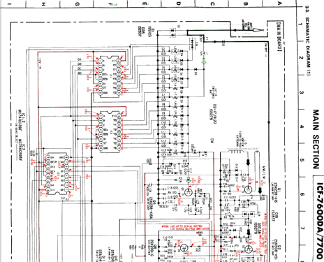
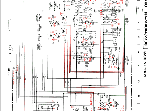
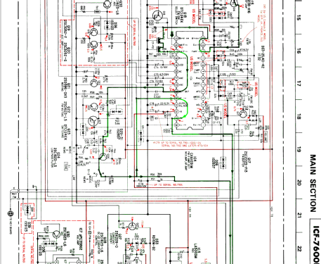
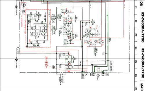
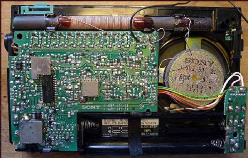
Main circuit components
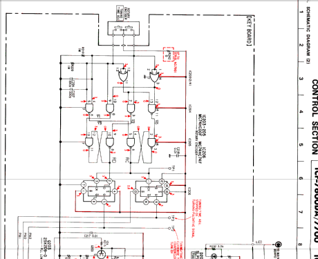
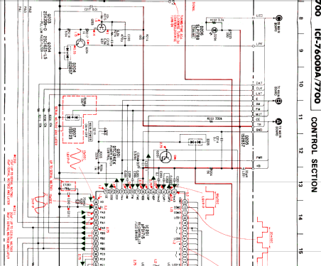
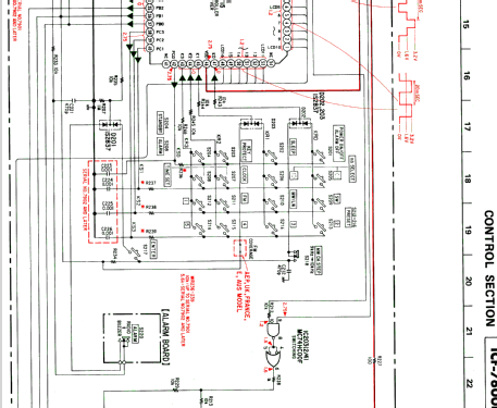
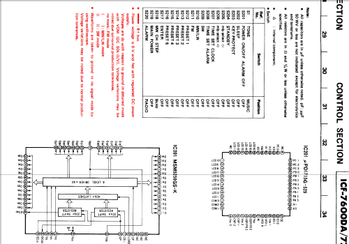
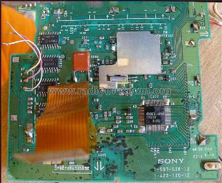
MCU PCB assembly
- PCB printed codes:
- Later units: 1-597-538-12 and 1-622-120-12
- Older units: 1-597-538-11 and 1-622-120-11
- Service Manual 1987.8 pn:
- A-3675-005-A (US, CAN, E) or
- A-3675-006-A (AEP, UK, FR, AUS)
- Service Manual SUPP-1 1988.1 additional pn:
- A-3675-008-A (ITA)
- IC201 UPD1715G-529 MCU with Pre-Scaler PLL Synthesizer and LCD Driver
- IC202 MSM5259GS-K Dot Matrix LCD Driver
- IC203 MC74HC00F Quad 2-Input NAND - Rotary Encoder for Tuning and Time adjust, LCD switching
- IC204 MC74HC00F Quad 2-Input NAND - Rotary Encoder for Tuning and Time adjust
- IC205 MC74HC00F Quad 2-Input NAND - Rotary Encoder for Tuning and Time adjust
- IC206 MC74HC74F Dual D-Flip-Flop - Rotary Encoder for Tuning and Time adjust
Receiver PCB
- PCB printed codes:
- Later units: 1-597-537-14 and 1-622-118-14
- Older units: 1-597-537-12 and 1-622-118-12
- Service Manual 1987.8 pn:
- A-3660-679-A (US, CAN, E) or
- A-3660-685-A (AEP, UK, FR, AUS)
- Service Manual SUPP-1 1988.1 additional pn:
- A-3660-743-A (ITA)
- Q1 2SK238 LW/MW RF Amp
- Q5 2SK238 SW RF Amp
- Q2 2SK508 1st Mixer Amp 10.7MHz IF output
- Q7 2SC2223 VCO(L) SW Osc
- Q6 2SK209 VCO(L) Buffer
- Q8 2SC2223 VCO(H) SW Osc
- Q6 2SK209 VCO(H) Buffer
- Q3 2SK209 2nd Mixer Amp 445kHz output
- Q4 2SC2223 2nd Osc 10.255MHz
- Q16 2SK238 FM RF Amp
- Q25, Q26 2SB624 - Power Control Switches
- IC1 TC74HC138F 3-to-8 Line Decoder - SW band selector
- IC2 TC74HC138F 3-to-8 Line Decoder - SW band selector
- IC3 MC74HC595F 8-bit Shift Register with Latched 3-State Outputs - SW band selector
- IC4 CXA1031M (CXA1019M on -14 PCBs) - FM/AM Receiver
- IC5 LA5003M 9C4 3V LDO Voltage Regulator - +3VDC TR receiver
- IC6 S-81230AG-R8 H5 3V LDO Voltage Regulator - +3VDC +B to MCU PCB assy
- IC7 UPC358G2 (s/n 7902 and later) Dual Opamps - AGC Amp
- RV2 1K Trimmer - AGC adjust
Undocumented proprietary Sony IC's
Some Sony integrated circuits were never publicly documented and were produced to be exclusively deployed on Sony equipment.
The CXA1031M used in this model seems to fall into this category, as it seems to be impossible to find a datasheet where the specifications can be consulted.
Although later in the production cycle of this model, Sony apparently decided to use the common, well documented, CXA1019M IC to replace the CXA1031M listed in the Service Manual.
This is the case of my unit with s/n 104566 and PCB printed codes 1-597-537-14 and 1-622-118-14. I can confirm that the IC4 was not tampered after the unit left the factory, as the soldered pins looks absolutely original.
Also, my unit sensitivity is on par with similar models I have with me.
I didn't check the circuit around CXA1019M against the Service Manual, so I can´t tell where it can replace the original CXA1031M without circuit modification. However, the pinout seems to be identical.
Jose Mesquita, 23.Jul.22