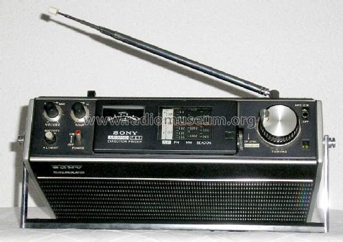
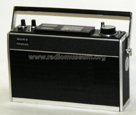
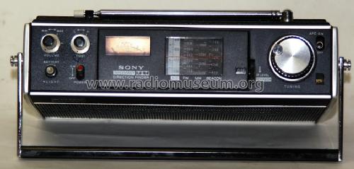
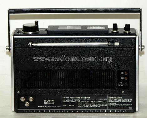
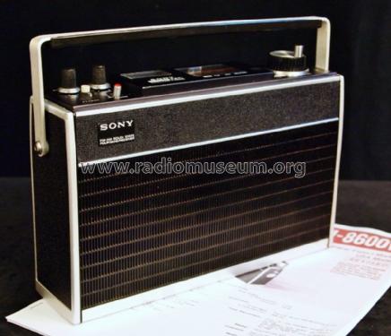
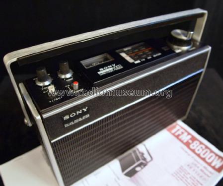
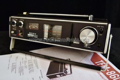
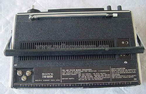
FM-AM Solid State Four Band Receiver TFM-8600W
Sony Corporation; Tokyo
- Country
- Japan
- Manufacturer / Brand
- Sony Corporation; Tokyo
- Year
- 1972 ?
- Category
- Broadcast Receiver - or past WW2 Tuner
- Radiomuseum.org ID
- 75233


Ebay User kewa27 Item 120885452086
Ebay User kewa27 Item 120885452086
Ebay User kewa27 Item 120885452086
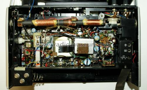
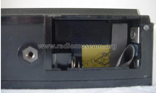
Innenansicht, Rückwand entfernt
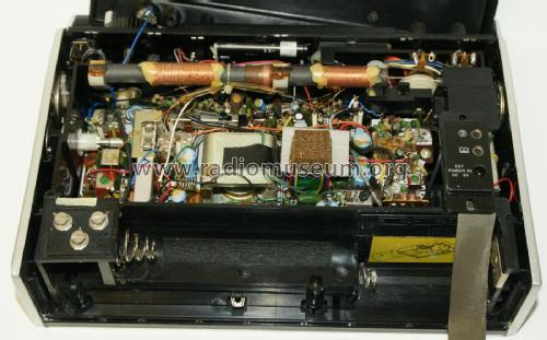
Innenansicht, Rückwand entfernt
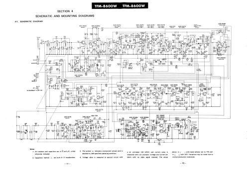
Click on the schematic thumbnail to request the schematic as a free document.
- Number of Transistors
- 23
- Main principle
- Superheterodyne (common); ZF/IF 455/10700 kHz
- Wave bands
- Wave Bands given in the notes.
- Power type and voltage
- Batteries / addl. power jack / D: 4 x 1.5 / DC 6 Volt
- Loudspeaker
- Permanent Magnet Dynamic (PDyn) Loudspeaker (moving coil) / Ø 10 cm = 3.9 inch
- Material
- Plastics (no bakelite or catalin)
- from Radiomuseum.org
- Model: FM-AM Solid State Four Band Receiver TFM-8600W - Sony Corporation; Tokyo
- Shape
- Portable set > 8 inch (also usable without mains)
- Dimensions (WHD)
- 252 x 162 x 72 mm / 9.9 x 6.4 x 2.8 inch
- Notes
-
covering LW 150 - 400 kHz, MW 530 - 1605 kHz, FM 87,5 - 108 MHz, Air Band 108 - 136 MHz AM; LW band and ferrite antenna to be used for locating NDBs; AFC, squelch.
Each transistor and diode type is only listed once.
- Net weight (2.2 lb = 1 kg)
- 1.9 kg / 4 lb 3 oz (4.185 lb)
- Literature/Schematics (1)
- -- Original-techn. papers. (parts list dated July 1972)
- Author
- Model page created by Martin Bösch. See "Data change" for further contributors.
- Other Models
-
Here you find 4077 models, 3934 with images and 977 with schematics for wireless sets etc. In French: TSF for Télégraphie sans fil.
All listed radios etc. from Sony Corporation; Tokyo
Collections
The model FM-AM Solid State Four Band Receiver is part of the collections of the following members.
Forum contributions about this model: Sony Corporation;: FM-AM Solid State Four Band Receiver TFM-8600W
Threads: 1 | Posts: 1
Zur Entfernung der Rückwand sind drei Schrauben zu lösen, die beiden klar sichtbaren oberhalb der Antennenanschlüsse resp. rechts unterhalb der Fremdspannungsbuchse.
Die dritte Schraube liegt gleich neben dem Antennenfuss, die kleine Schraube am Widerlager der Teleskopantenne muss nicht gelöst werden.
Die Rückwand wird dann hinten, unten beim Batteriefach aus der Führung gezogen, dann links angehoben. In der rechten oberen Ecke, unterhalb des Tonreglers resp. bei der Antennenspitze, wird die Rückwand von einer Kunststoffnase zurückgehalten, die unter dem Geräterahmen eingehängt ist, bei Gewaltanwendung bricht sie ab.
hope that helps Martin Bösch
Martin Bösch, 23.Dec.14