- Paese
- Australia
- Produttore / Marca
- Standard Telephones and Cables Pty, Ltd (STC), Sydney
- Anno
- 1936
- Categoria
- Radio (o sintonizzatore del dopoguerra WW2)
- Radiomuseum.org ID
- 335136
Clicca sulla miniatura dello schema per richiederlo come documento gratuito.
- Numero di tubi
- 5
- Principio generale
- Supereterodina (in generale); ZF/IF 450 kHz; 2 Stadi BF
- N. di circuiti accordati
- 6 Circuiti Mod. Amp. (AM)
- Gamme d'onda
- Onde medie (OM) e corte (OC).
- Tensioni di funzionamento
- Batterie (di accumulatori e/o a secco) / 3 x 45 & 2 Volt
- Altoparlante
- AP magnetodinamico (magnete permanente e bobina mobile) / Ø 8 inch = 20.3 cm
- Materiali
- Mobile in legno
- Radiomuseum.org
- Modello: 526B Ch= 52B - Standard Telephones and Cables
- Forma
- Console di qualsiasi tipo
- Annotazioni
-
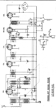
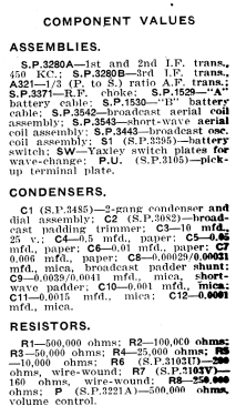
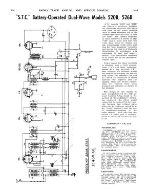
STC Models 520B & 526B are 5-valve receivers designed for dual-wave coverage and operation from battery power supplies. Both these receivers are console-style. The chassis employed in these receivers are known as type “52B” and is fitted with four controls, these being volume, tuning, wave-change (with the extra position for “local broadcast” reception & section for control of dial-scale illumination in accordance with waveband in use) & battery switch.
The loudspeaker employed is an 8-inch unit of the permanent magnet type.Power supply for these receivers is obtained from a 2-volt accumulator “A” & three series-connected 45-volt dry batteries “B”.
Bias voltages are obtained within the receiver utilizing the voltage drop across two resistors (R6 & R7) which are connected in series between “B” negative and the chassis. Only four battery connections are required, those being grouped and coloured as shown on the diagram.The design of the chassis is quite straightforward, the only unusual features being found in the method of “local/distance” switching employed (the direct aerial connection is replaced by the capacity between two twisted wires when the wave-change switch is in the local position), and in the use of transformer-coupling in the audio channel.
Note that the second IF valve grid is returned direct to earth and receives no bias at all.Radio Trade Annual 1939, Page 324.
See also Model 520B with the same chassis, but different cabinet style.
- Letteratura / Schemi (1)
- -- Original-techn. papers. (Schematic.)
- Letteratura / Schemi (2)
- Radio Trade Annual of Australia (6th Edition 1938. Page 324)
- Autore
- Modello inviato da Martin Kent. Utilizzare "Proponi modifica" per inviare ulteriori dati.
- Altri modelli
-
In questo link sono elencati 616 modelli, di cui 272 con immagini e 306 con schemi.
Elenco delle radio e altri apparecchi della Standard Telephones and Cables Pty, Ltd (STC), Sydney