AF/RF Signal Generator 67A
Taylor Electrical Instruments Ltd.; Slough, Dover
- Land
- Grossbritannien (UK)
- Hersteller / Marke
- Taylor Electrical Instruments Ltd.; Slough, Dover
- Jahr
- 1955 ??
- Kategorie
- Service- oder Labor-Ausrüstung
- Radiomuseum.org ID
- 98796

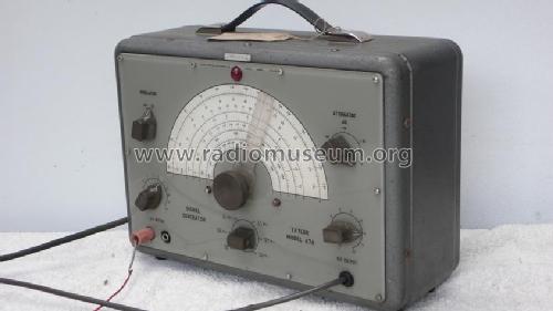
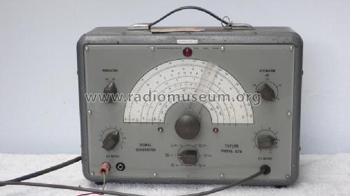
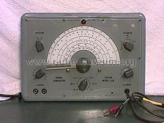
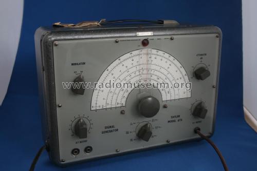
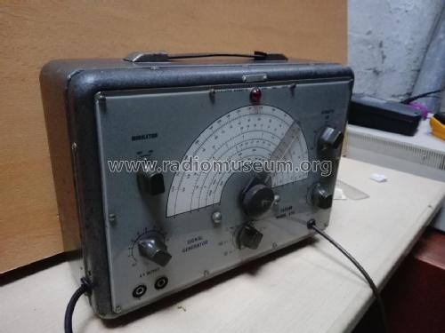
Taylor 67A generator, front
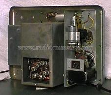
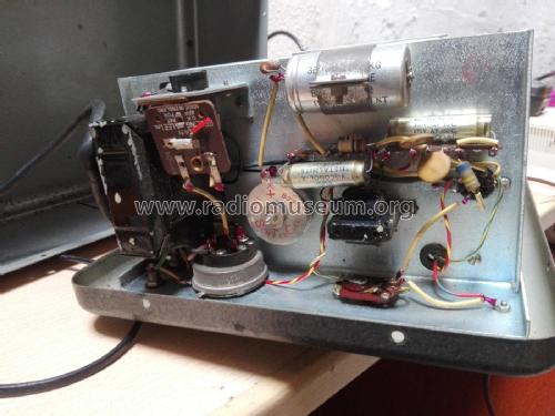
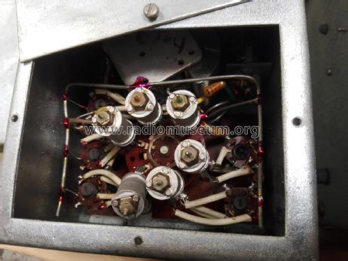
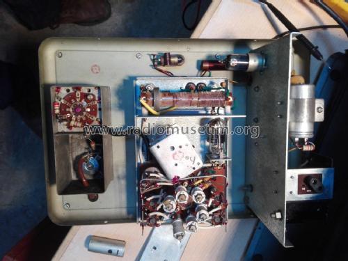
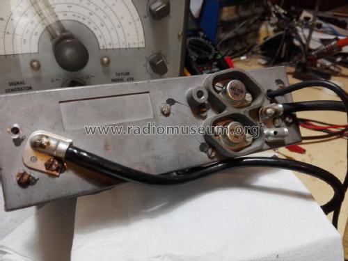
Taylor 67A generator, inside

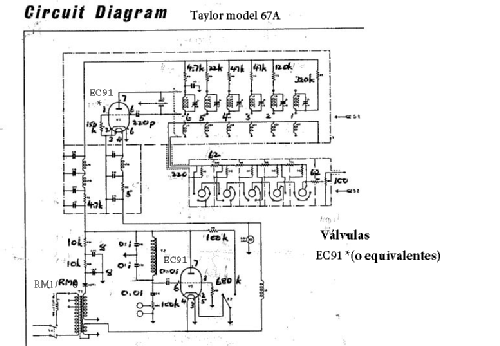
Klicken Sie auf den Schaltplanausschnitt, um diesen kostenlos als Dokument anzufordern.
- Anzahl Röhren
- 2
- Anzahl Kreise
- 1 Kreis(e) AM
- Wellenbereiche
- - ohne
- Betriebsart / Volt
- Wechselstromspeisung / 115; 210; 240 Volt
- Lautsprecher
- - - Kein Ausgang für Schallwiedergabe.
- Material
- Metallausführung
- von Radiomuseum.org
- Modell: AF/RF Signal Generator 67A - Taylor Electrical Instruments
- Form
- Tischmodell, Zusatz nicht bekannt - allgemein.
- Abmessungen (BHT)
- 330 x 238 x 145 mm / 13 x 9.4 x 5.7 inch
- Bemerkung
-
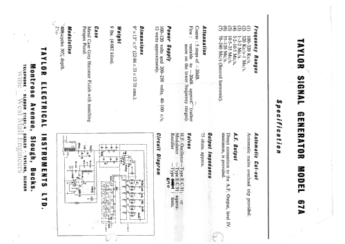
Frequency range 100 kHz-120MHz in 6 ranges. Range switch says highest range goes up to 240 MHz, but this is 2nd harmonic. Simple instrument. Output is coupled to tuned circuit so frequency stability is poor. Internal fixed frequency oscillator for modulation. Selenium rectifier for power supply.
The voltage selector is located inside the device.
- Autor
- Modellseite von Onno Massar angelegt. Siehe bei "Änderungsvorschlag" für weitere Mitarbeit.
- Weitere Modelle
-
Hier finden Sie 44 Modelle, davon 43 mit Bildern und 16 mit Schaltbildern.
Alle gelisteten Radios usw. von Taylor Electrical Instruments Ltd.; Slough, Dover
Sammlungen
Das Modell AF/RF Signal Generator befindet sich in den Sammlungen folgender Mitglieder.