- Produttore / Marca
- Tecsun 德生通用电器制造有限公司 Tecsun General Electric Manufacturing Co., Ltd; Dongguan (Guangdong, SC)
- Anno
- 2014 ?
- Categoria
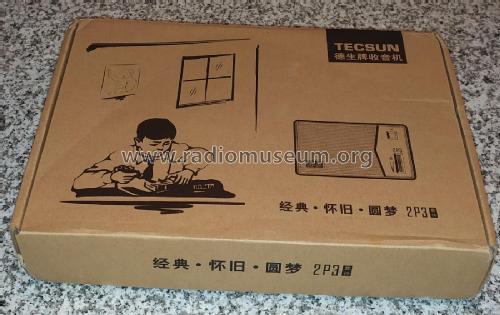
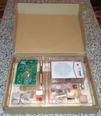
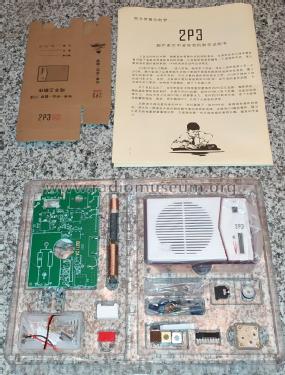
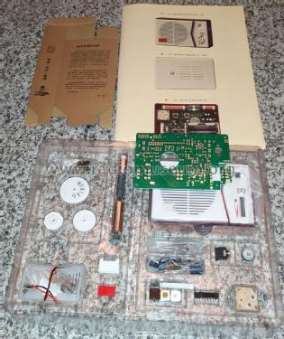
- Kit, scatola di montaggio (parti sfuse e istruzioni o solo istruzioni di montaggio)
- Radiomuseum.org ID
- 302481


From Tecsun marketing pictures
Bought from a Chinese seller Aug-2021.
Bought from a Chinese seller Aug-2021.
Bought from a Chinese seller Aug-2021.
Bought from a Chinese seller Aug-2021.
Bought from a Chinese seller Aug-2021.
Clicca sulla miniatura dello schema per richiederlo come documento gratuito.
- Numero di transistor
- 3
- Principio generale
- Supereterodina (in generale); ZF/IF 455 kHz
- Gamme d'onda
- Solo onde medie (OM).
- Tensioni di funzionamento
- Batterie a secco / AA: 2 x 1.5 Volt
- Altoparlante
- AP magnetodinamico (magnete permanente e bobina mobile) / Ø 7 cm = 2.8 inch
- Potenza d'uscita
- 0.12 W (max.)
- Materiali
- Plastica (non bachelite o catalina)
- Radiomuseum.org
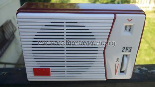
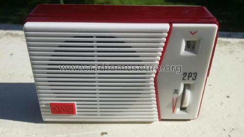
- Modello: 2P3 - Tecsun 德生通用电器制造有限公...
- Forma
- Tascabile (portatile molto piccola), < 20 cm
- Dimensioni (LxAxP)
- 110 x 75 x 35 mm / 4.3 x 3 x 1.4 inch
- Annotazioni
-
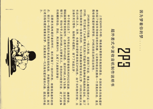
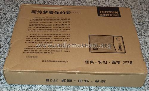
The original 2P3 diy kit radio was developed in the mid 1960's. This is the new 2014 2P3 diy kit radio, retaining the old style case but with updated chassis and components.
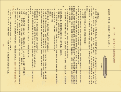
The Chinese building guide is comprehensive and detailed, incuding a very detailed section on how to align the radio to get the maximum signal possible. There is a publicly available English translation made by CRKITS covering the 2014.3 Ver. 4 "Green PCB" variant. That said, this is not an electronics beginner's kit..
Main features
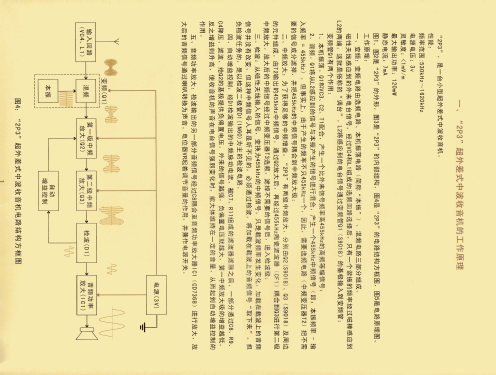
- Frequency coverage: MW 530 - 1620 kHz
- Sensitivity: < 1 mV/m
- Maximum audio output: 120 mW
- Quiescent current: 7 mA
Some technical details
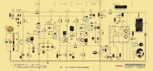
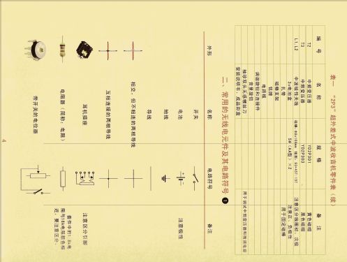
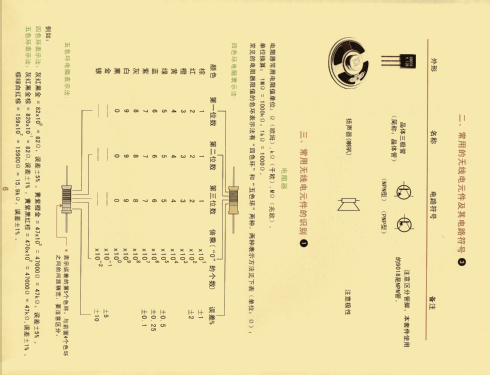
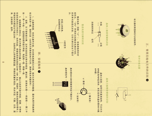
The RF section is handled by three silicon transistors, the detection is handled by a germanium 1N60 diode, and the audio uses one CD7368 IC.
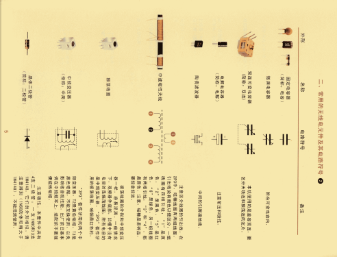
Q1 is the RF amplifier/mixer/oscillator, and Q2 and Q3 supports the two IF stages where a 455 kHz ceramic filter helps improving the selectivity, besides the three canned RF transformers (one oscillator in red, one 1st IF in yellow, and one 3rd IF in black).
The ferrite antenna uses three coil configuration to allow fine adjustment for maximum signal reception on both low and high RF frequencies.
The detection circuit built around the 1N60 diode is shielded.
The power supply lines are RC decoupled for a total of three Vcc lines, where the 3rd line at 1.7VDC used to bias the RF transistors is stabilized with three 1N4148 diodes in series.
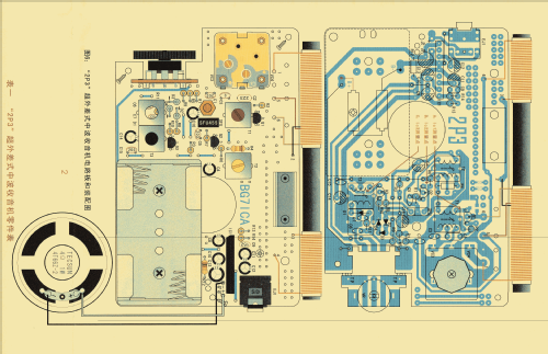
The three RF transistor collector Vcc lines (marked as A, B, C, in the diagram) comes in open circuit in the PCB to allow for current checking and test for build errors. These test points need to be short-circuited with solder in order to have a fully functional circuit.
- Prezzo nel primo anno
- 35.00 USD
- Autore
- Modello inviato da Didier Tholomier. Utilizzare "Proponi modifica" per inviare ulteriori dati.
- Altri modelli
-
In questo link sono elencati 36 modelli, di cui 35 con immagini e 22 con schemi.
Elenco delle radio e altri apparecchi della Tecsun 德生通用电器制造有限公司 Tecsun General Electric Manufacturing Co., Ltd; Dongguan (Guangdong, SC)
Collezioni
Il modello fa parte delle collezioni dei seguenti membri.
Discussioni nel forum su questo modello: Tecsun 德生通用电器...: 2P3
Argomenti: 1 | Articoli: 1
This is a English translation from the original Chinese building instructions for the checking and adjusting procedures.
I have used a OCR tool to extract the Chinese text from the public available pictures of the building instructions and then used Google to help with the translation.
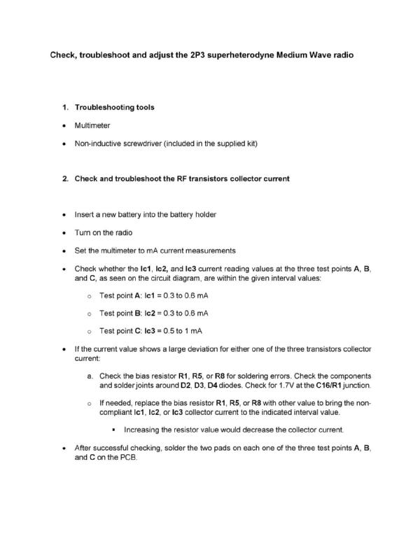


Jose Mesquita, 10.Sep.21