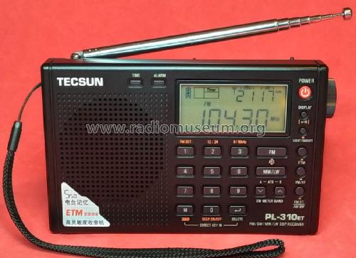
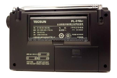
FM/SW/MW/LW DSP Receiver PL-310ET
Tecsun 德生通用电器制造有限公司 Tecsun General Electric Manufacturing Co., Ltd; Dongguan (Guangdong, SC)
- Fabricante / Marca
- Tecsun 德生通用电器制造有限公司 Tecsun General Electric Manufacturing Co., Ltd; Dongguan (Guangdong, SC)
- Año
- 2014 ?
- Categoría
- Radio - o Sintonizador pasado WW2
- Radiomuseum.org ID
- 325003


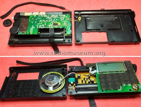

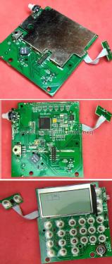
Exploded parts view.

User manual
Haga clic en la miniatura esquemática para solicitarlo como documento gratuito.
- Numero de transistores
- Hay semiconductores.
- Semiconductores
- Principio principal
- DSP, Digital Signal Processor
- Gama de ondas
- OM, OL, más de dos OC y FM
- Tensión de funcionamiento
- Pilas + jack (etc.) para alimentación externa. / 3.7 / 4.5 Volt
- Altavoz
- Altavoz dinámico (de imán permanente) / Ø 5.7 cm = 2.2 inch
- Potencia de salida
- 0.18 W (max.)
- Material
- Plástico moderno (Nunca bakelita o catalina)
- de Radiomuseum.org
- Modelo: FM/SW/MW/LW DSP Receiver PL-310ET - Tecsun 德生通用电器制造有限公...
- Forma
- Portátil de bolsillo , menor de 20cm.
- Ancho, altura, profundidad
- 141 x 87 x 30 mm / 5.6 x 3.4 x 1.2 inch
- Anotaciones
-
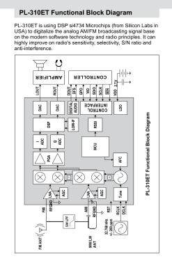
This is a DSP world pocket radio based on the Silicon Labs Si4734 receiver IC. It features a Clock with Sleep timer and Alarm, offering FM stereo when using headphones.
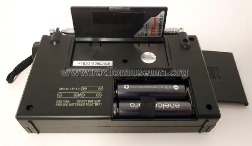
It runs with 4.5Volt from three UM3 AA dry batteries, or else with 3.7Volt from three Ni-MH UM3 AA rechargeable batteries (It can be set to use the built-in USB charger as well).
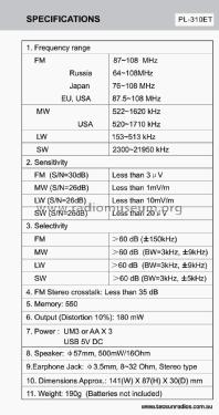
Main specifications:
- FM: Selectable between 87.5-108 MHz (EU/USA), or 64-108 MHz (Russia), or 76-108 MHz (Japan)
- MW: Selectable between 522-1620 kHz at 9 kHz steps, or 520-1710 kHz at 10 kHz steps (USA)
- LW: 153-513 kHz
- SW:2300-21950 kHz
- AM Bandwith: Selectable between 6, 4, 3, 2, and 1 kHz
- Sensitivity: FM: <3 μV, MW <1 mV/m, LW <10 mV/m, SW <20 μV
- 550 memories to store radio stations.
- Audio output: 180 mW@10% distortion
- Speaker: 500 mW, 16 Ω
- Earphone Jack: 3.5 mm, 8 to 32 Ω, Stereo
- Power Supply: UM3 or AA x 3, or USB 5V DC
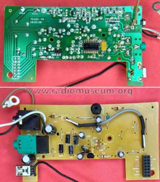
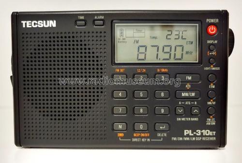
In terms of design, this radio uses two main PCBs, the analog PCB at the rear side, and the digital PCB at the front side.
In the analog PCB: The SW signal from the antenna is shaped by two JFET (Q1 and Q2) in the RF front-end and passed to the Si4734 IC. The MW and FM signals are passively shaped and passed to the Si4734 IC. The CD1622CB stereo audio amplifier IC receives the L-R channels from the Si4734 IC in the digital PCB. A 2.7V power regulator IC (IC1) supplies energy for the MCU in the digital PCB. Semiconductor power switches are used to apply energy to the SW front-end, and to the audio amplifier.
In the digital PCB: A Renesas R5F2L38ACDFP MCU manages all the radio operation, with the help of a LCD Display, a Keyboaard, two rotary encoders (Volume and Tuning), one TC24C32 EEPROM, a 32.768MHz crystal, a 0.22F/5.5V SuperCapacitor to store the 2.7V supply, a KLJ-8530 Dynamic Buzzer, and the Silicon Labs Si4734 radio receiver IC.
- Peso neto
- 0.190 kg / 0 lb 6.7 oz (0.419 lb)
- Autor
- Modelo creado por Jose Mesquita. Ver en "Modificar Ficha" los participantes posteriores.
- Otros modelos
-
Donde encontrará 36 modelos, 35 con imágenes y 22 con esquemas.
Ir al listado general de Tecsun 德生通用电器制造有限公司 Tecsun General Electric Manufacturing Co., Ltd; Dongguan (Guangdong, SC)
Colecciones
El modelo FM/SW/MW/LW DSP Receiver es parte de las colecciones de los siguientes miembros.