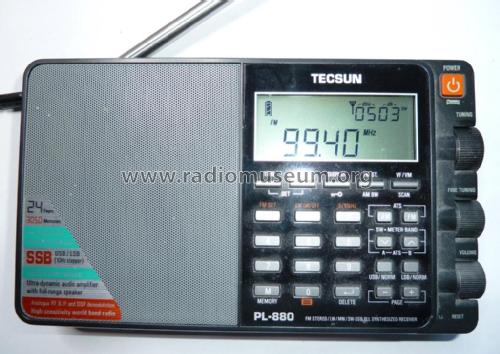
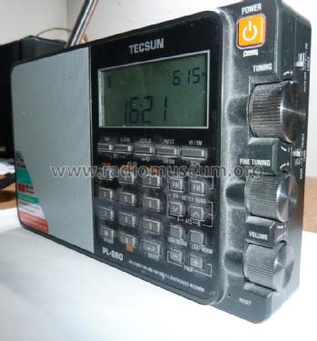
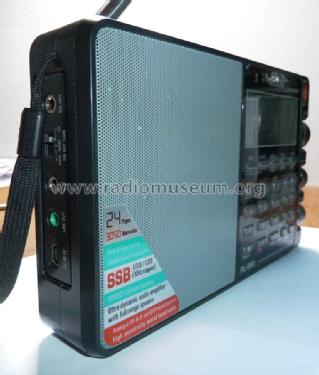
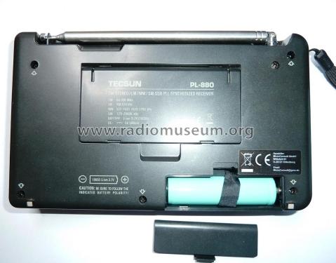
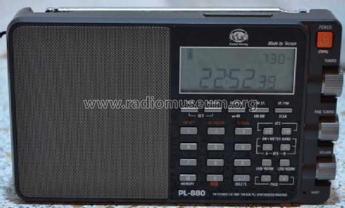
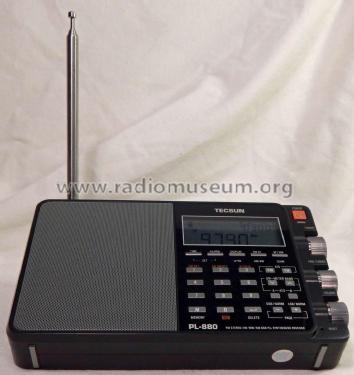
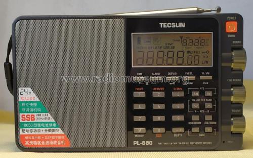
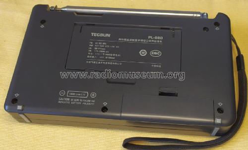
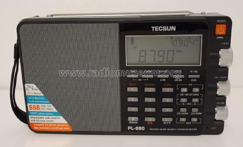
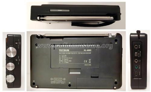
FM Stereo/LW/MW/SW-SSB PLL Synthesized Receiver PL-880
Tecsun 德生通用电器制造有限公司 Tecsun General Electric Manufacturing Co., Ltd; Dongguan (Guangdong, SC)
- Fabricant / Marque
- Tecsun 德生通用电器制造有限公司 Tecsun General Electric Manufacturing Co., Ltd; Dongguan (Guangdong, SC)
- Année
- 2013 ?
- Catégorie
- Radio - ou tuner d'après la guerre 1939-45
- Radiomuseum.org ID
- 246703


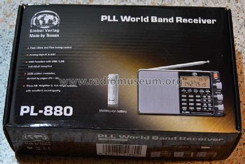


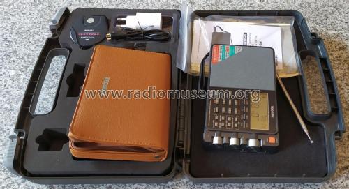
Carrying hard case

Carrying hard case


Cliquez sur la vignette du schéma pour le demander en tant que document gratuit.
- Principe général
- PLL (Phase-locked Loop, boucle à phase asservie)
- Gammes d'ondes
- PO, GO, plus que 2 x OC et FM
- Tension / type courant
- Batteries / Alim. BT séparée avec fiche / Li-Ion: 3.7 / 5 Volt
- Haut-parleur
- HP dynamique à aimant permanent + bobine mobile / Ø 4 cm = 1.6 inch
- Puissance de sortie
- 0.45 W (qualité inconnue)
- Matière
- Plastique moderne (pas de bakélite, ni de catalin)
- De Radiomuseum.org
- Modèle: FM Stereo/LW/MW/SW-SSB PLL Synthesized Receiver PL-880 - Tecsun 德生通用电器制造有限公...
- Forme
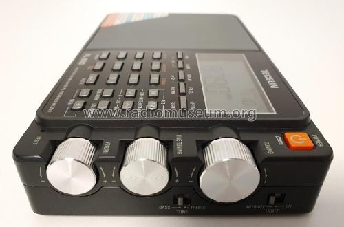
- Portable, appareil de poche. Taille < 20cm
- Dimensions (LHP)
- 192 x 113 x 33 mm / 7.6 x 4.4 x 1.3 inch
- Remarques
-
The Tecsun FM Stereo/LW/MW/SW-SSB PLL Synthesized Receiver is a PLL triple conversion superheterodyne using digital signal processing decoding for the Amplitude Modulation (AM/SW) bands. The FM band is handled directly by the DSP system.
The 1st and 2nd RF heterodyne conversion stages are analog designs controlled digitally by a PLL system. The 3rd and final conversion and decoding stage is handled in the digital domain by a SiLabs 4735-D60 IC that also handles the FM band reception.
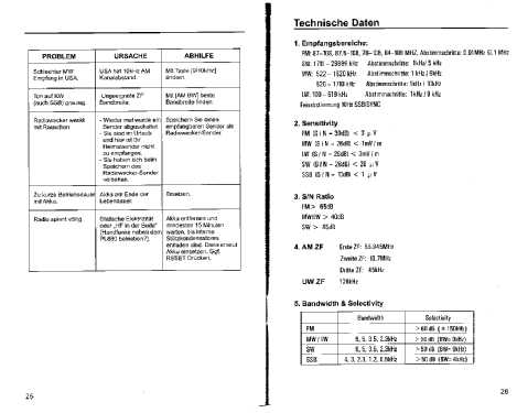
Empfangsbereiche:
FM 87-108MHz, 76-108MHz, 64-108MHz, Abstimmschritte 0,01/0,1MHz.
SW 1711-29999kHz, Abstimmschritte 1kHz/5kHz.
MW 520-1710, Abstimmschritte 1kHz/10kHz.
522-1620, Abstimmschritte 1kHz/9kHz.
LW 100-519kHz, Abstimmschritte 1kHz/9kHz.
Feinabstimmung SSB/Sync 10/50Hz.
3-fach Superhet,
1. ZF: 55.845MHz,
2. ZF: 10.7MHz,
3. ZF: 45kHz (AM)UKW-ZF: 128kHz.
Schaltbare ZF-Filter:
MW/LW 9, 5, 3.5, 2.3kHz.
SW 9, 5, 3.5, 2.3kHz.
SSB 4, 3, 2.3, 1.2, 0.5kHz
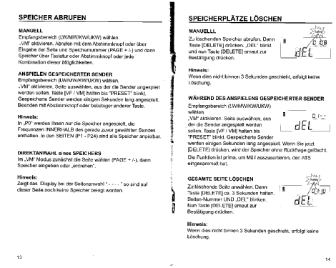
Speicherplätze: 3050 total.
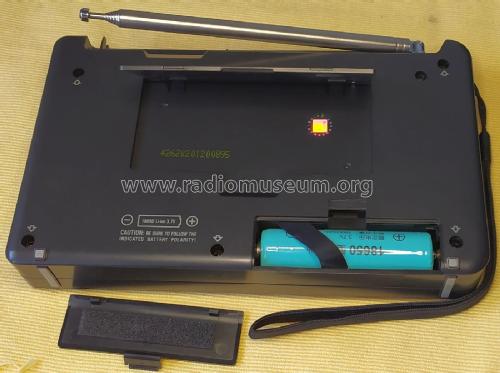
Stromversorgung: Akku Li-Ion 3,7 Volt, Typ 18650,
Ladeanschluß USB DC 5 Volt, 300mA
- Poids net
- 0.520 kg / 1 lb 2.3 oz (1.145 lb)
- Prix de mise sur le marché
- 179.00 Euro
- Auteur
- Modèle crée par Michael Schott †. Voir les propositions de modification pour les contributeurs supplémentaires.
- D'autres Modèles
-
Vous pourrez trouver sous ce lien 36 modèles d'appareils, 35 avec des images et 22 avec des schémas.
Tous les appareils de Tecsun 德生通用电器制造有限公司 Tecsun General Electric Manufacturing Co., Ltd; Dongguan (Guangdong, SC)
Collections
Le modèle FM Stereo/LW/MW/SW-SSB PLL Synthesized Receiver fait partie des collections des membres suivants.
Contributions du forum pour ce modèle: Tecsun 德生通用电器...: FM Stereo/LW/MW/SW-SSB PLL Synthesized Receiver PL-880
Discussions: 3 | Publications: 4
A number of non official, non-documented, hidden, additional features have been disclosed as available on some of the model revisions, namely when they have firmware version 8820 installed. The following list covers those and other overlooked features.
| # | Feature | Power state | Key | Band | Procedure |
| 1 | Enable additional features | ON | "4" | AM LW SW | To be able to enable Muting Threshold and DNR, enable this option. Select "AM" or "SW", press&hold key "4" until "ON" or "OFF" is shown. |
| 2 | FM de-emphasis | ON | "5" | Select "FM", press&hold key "5" until "50" (Europe) or "75" (USA) is shown. | |
| 3 | Dynamic Noise Reduction | ON | "6" | Enable additional features (see #1). Press&hold key "6" until "ON" or "OFF" is shown; press key "6" to change (500Hz narrow band filter is not available when DNR is enabled) | |
| 4 | Line Out level | ON | "7" | Select "AM" or "FM". Press&hold key "7" until the current level is shown; use Tuning knob to adjust the required value (30 to 63). Not available on SW band. | |
| 5 | Muting threshold | ON | "9" | AM FM | Enable additional features (see #1). Select either "FM", "AM", "SW" or "SSB" (dedicated threshold levels for each). Press&hold key "9" until the current threshold level is shown; use Tuning knob to adjust it (00 to 40 dBu where 00 disables muting); press key "9" to change. |
| 6 | Center calibration and/or SSB zero beat calibration | ON | "0" and/or "Snooze" | AM(MW) SW |
Tecsun method: Select either LSB or USB; tune to a AM broadcast station and zero-beat using Fine Tuning for minimal distortion and audio is natural; if the last 2-digits of frequency are not "00", press&hold key "Snooze" to calibrate it where "00" will be shown when completed. Alternative method: Press "Display" to show the signal indicator; select either "AM" or "SW"; press "USB"; press&hold key "0" until a 2-digit number is shown blinking as well as the Hz digits of the tuned frequency; release key "0"; use Fine Tuning to adjust; press key "0" to set; repeat the above for "LSB" mode; check to have the same tone when tuned to nnn.95 USB and nnn.05 LSB; repeat the above as needeed. Note on AM/MW weak reception due to off-center calibration: According to Bill (Radio-TimeTraveller), additional +5 to +6dB can be acquired by using the fine tuning knob to tune around the radio station known frequency. In his radio the center frequency on MW is off by 2kHz, as on each station he needed to tune up 2 kHz. This issue seems to be unrelated to the SSB calibration. |
| 7 | Bandwidth scrolling | ON | "AM BW" | Press "AM BW" and immediately use either the Tuning or Fine Tuning knobs to scroll through the values. | |
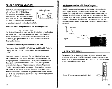
| 8 | SSB Sync Detetion | ON | "USB" "LSB" | Press&hold either key "USB" or "LSB" until "SYNC" is shown; press the same key to disable it. | |
| 9 | External MW/LW antenna | ON | "AM" | MW | A Reset may be required. To use this feature, tune only upwards, so tune the station before proceeding. Toggles between internal magnetic antenna and external SW antenna socket. Press "AM" and tune to a station; press "USB"; press "AM" (if LW is enabled, press "AM" again); press "USB"; press "FM"; press "USB"; press "USB"; switch between internal or external antenna pressing "AM" or "SW". To return to normal, tune down. |
| 10 | 1 kHz bandwidth filter | ON | MW SW | Enable additional features (see #1). Select the required SW band. Set the Muting threshold (see #5) to 13 or above; disable additional features (see #1); enable additional features (see #1); press "AM BW" to see the 1 kHz filter; it will be enabled until "AM BW" is pressed again; | |
| 11 | FM range | OFF | "1" | Press&hold key "1" until 88-108, 76-108, or 87-108 MHz is shown; press key "1" to set. | |
| 12 | LW band | OFF | "2" | To enable/disable LW band, press&hold key "2" until "ON" or "OFF" is shown. | |
| 13 | MW 9/10 kHz steps | OFF | "3" | To set the MW tuning step, press&hold key "3" until "9kHz" or "10kHz" is shown. | |
| 14 | Battery low voltage shutdown | OFF | "4" | Press&hold key "4" until the current low voltage shutdown limit is shown; use Tuning knob to adjust the value (3.4 to 3.7 Volt); press key "4" to set. | |
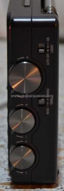
| 15 | LCD backlight | OFF | "5" | Toggles the backlight between "ON (Auto Off)" or "OFF". Press&hold key "5" to toggle between "ON" (same as Auto Off using the slider Switch) and "OFF" (backlight turned off). | |
| 16 | Show Seconds | "8" | Press&hold key "8" until Seconds digits are shown on the clock. | ||
| 17 | Firmware version | OFF | "AM BW" | Press&hold key "AM BW" until all LCD segments are lit; press key "AM BW" to show Firmware version (8819 or 8820); press key "AM BW" to show the Firmwaree release date using dd-mm-yy format (recent chassis revisions will not show the date). | |
| 18 | Runtime since battery charge/Reset | OFF | "VF/VM" | Press&hold key "VF/VM" until the runtime is shown since the last time the battery was charged or since the last time the radio was reset. | |
| 19 | Days since first power ON | OFF | "VF/VM" | Press&hold key "VF/VM" until the runtime is shown; press key "VF/VM" to show the number of days (upper right) since the radio was new and battery was first installed. | |
Jose Mesquita, 03.Jun.22
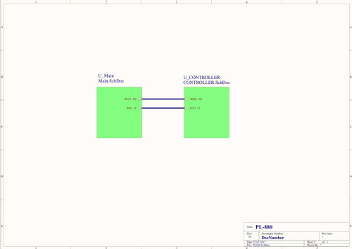
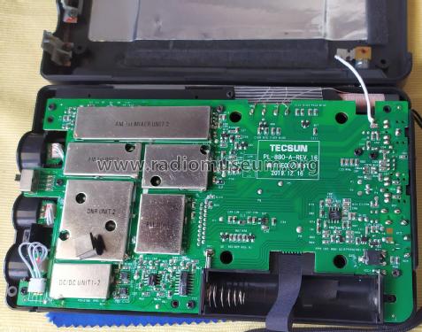
The Tecsun PL-880 uses two PCB assemblies:
- MCU/DISPLAY/KB PCB Assembly identified as "PL-880-B-REV.n"
- Receiver PCB Assembly identified as "PL-880-A-REV.n"
- where "n" is the release number.
The followwing partial parts listing with remarks covers the PCB assemblies for the MCU "PL-880-B-REV.10" and Receiver PCB "PL-880-A-REV.12". Component labels of MCU PCB are prefixed with "2" as seen on the board silkscreen labels.
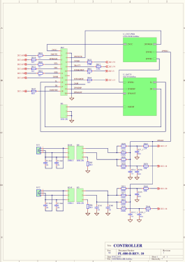
MCU PCB "PL-880-B-REV.10"
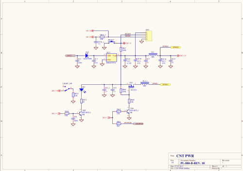
- Power Control
- 2D2 BAS140W schottky diode - From VCC to IC3
- 2IC3 RH5Z27CA? 3-pin smd LDO power regulator - From VCC to Power lines
- 2Q5 SE2301 3-pin smd MOSFET - Switch Power on/off
- 2D1 LED LCD backlight
- 2Q2 S9014 3-pin smd npn - Switch for 2D1 LED on/off
- 2C4 Super Capacitor
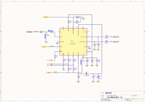
- DSP processor
- IC4 Si4735-D60 DSP receiver - FM RF signal decoding, MW/SW 10700 kHz IF signal decoding
- MCU Processor
- 2IC1 R5F2L38ACDFP Renesas 96KB ROM, 1KBx4 Data Flash, 10KB RAM, MCU processor in 80-pin PLQP0080KB-A smd package
- 2IC2 BL24C256 256Kbit Serial EEPROM 8-pin smd
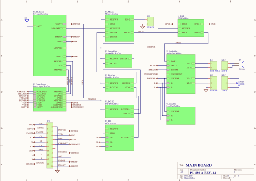
Receiver PCB "PL-880-A-REV.12"
- RF Front-End
- D1, D2 1N4148 diodes - Antenna over-voltage protection
- Q26 BF510 3-pin FET smd - MW RF front-end
- Q4 2SK2394-Y7 3-pin FET smd - SW RF front-end
- D6, D5 1SS135 smd diodes - Join MW RF andd SW RF signals to send to 1st Mixer
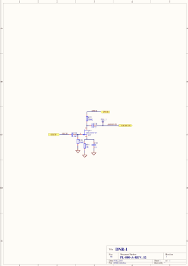
- Q6, Q5 L8050HQLT1 3-pin smd npn - Enabless "DNR1" AGC line to control RF gain by inserting C12 between D6,D5 outputs and ground.
- 1st and 2nd Mixers
- Q7, Q8 2SK2394-Y7 3-pin FET smd - 1st Mixer with 55845 kHz IF output
- Q9 BF510 3-pin smd - 2nd Mixer with 10700 kHz IF output
- 1st Local Oscillator
- Q16 BF510 3-pin FET smd - Oscillator
- Q17 2SC3356 3-pin npn smd - buffer
- D9, D10 1SV101 smd varicaps
- 2nd Local Oscillator
- Q13 2SC3356 3-pin smd npn - Oscillator
- 1X2 45.145 MHz xtal
- D11 1SV101 varicap
- D12 BB133 varicap
- PLL Synthesizer
- IC6 MB15E03SLPFV1 16-pin smd - PLL Synthesizer
- 1X3 7.200 MHZ xtal
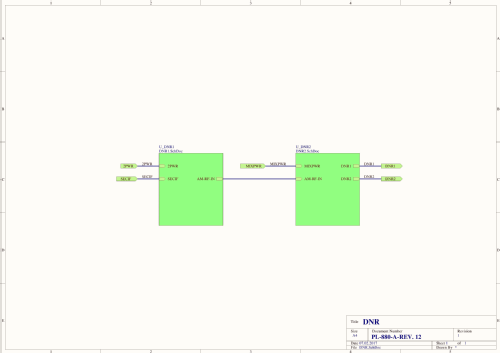
- Dynamic Noise Reduction (DNR)
- Q12 2SK2394-Y7 3-pin FET smd - 10700 kHz IF buffer
- IC4 CXA1691AM (CD1691CB) 28-pin smd AM/FM radio - Receives MW/SW 10700kHz IF signal, outputs AGC voltage at pin 22 marked as "DNR1" to
control the gainenable a low pass filter on the RF Input front-end. - Q20, Q21 S9014 3-pin smd npn - Together with VR3 500K pot, receives "DNR1" AGC and outputs distinct AGC level marked as "DNR2" to control filter response of the Audio Amplifier.
- 1X5 10.245 kHz xtal
- LBQ1 455 kHZ filter
- DC-DC Converter for tuning voltage
- Q23, Q24 S9014 3-pin npn smd - Oscillator, using transformer T881
- D8 1N4148 smd - HF rectifier
- D7 16V Zener diode smd - Regulation
- Power Supply
- D4 1N5819 schottky diode - From USB Power to VCC line
- Q20 2SJ245 3-pin smd MOSFET - Switch from BATT power to VCC line
- BT1 3.7V Battery
- Q14 SE2301 3-pin smd MOSFET - Battery charger circuit
- IC1 MCP73831 (or equiv.) 5-pin smd SOT23-5 - BT1 Battery charger
- IC2 RP114N281D 5-pin smd LDO 300mA, 2.8V power regulator
- Q10 SE2301 3-pin smd MOSFET - Switch to SW-Power
- Q11 SE2301 3-pin smd MOSFET - Switch to MW-Power
- Q2 SE2301 3-pin smd MOSFET - Switch to Audio Amp section
- Audio Amplifier
- IC8, IC9 TC4W53FU 8-pin smd 2-Channel Multiplexer/Demultiplexer - Switch between AM or FM distinct high pass filters.
- IC5 CLC2011 8-pin smp 2-channel opamp - Audio pre-amplifier (approx. gain of 5); receives L/R audio from the DSP IC via IC8/IC9 to drive IC7.
- IC7 SP2068EF(APA2068) 16-pin smp 2-channel audio power amplifier - Earphones (2-ch/stereo) and Speaker (bridged mode).
- Q18, Q19 S9014 3-pin smd npn - Enables "DNR2" AGC to control audio low pass filter shape by inserting C59/C57 (22nF) on RC networks at IC5 outputs.
- Line Out
- IC3 CLC2011 8-pin smp 2-channel opamp - Line audio amplifier (approx. gain of 6); receives L/R audio from the DSP IC to drive the Line Out socket.
Jose Mesquita, 02.Jun.22
Introduction on the reported issues for the PL-880
The PL-880 is a PLL triple conversion superheterodyne with digital signal processing (SiLabs 4735-D60) decoding on Amplitude Modulation (AM) bands. FM band is handled directly by the DSP.
I have been following the reports of owners, testers and modders concerning some alleged issues discovered since the model was relased back in 2013 up to present day (june-2022).
Most of the issues have been worked out by Tecsun (firmware and hardware updates) and Silicon Labs (DSP 4735 firmware).
One major issue has been reported for the usage of SSB, where audio distortion is experienced when using LSB/USB under certain signal level conditions, alleged caused by AGC bad behavior.
As the AGC function is implemented inside the SiLabs 4735 DSP integrated circuit, it seems that Tecsun was having a hard time minimizing the issue, after having released several harware versions of the Mainboard PCB assembly and at least two official firmware versions.
Some owners tell us that different behaviors have been discovered for the same displayed firmware version, so Tecsun may have been releasing "silent" updates on different production batches. Also the later production releases only shows the firmare version, omitting the release date.
Currently there is no consensus from buyers concerning the SSB issues being fixed or pending. Some say the issues are there, others comment that the problem was fixed. As Tecsun released so many different hardware and firmwware versions it is possible that some vendors still sell the older batches, but there is no positive confiormation that the issue was fixed and for what hardware/firmware version.
Due to the above PL-880 behavior, many prefer the PL-660 or PL-680 double conversion pure analog/PLL designs for SSB listening . I have the PL-680 but do not have the PL-880 yet.
Additionally, the USB/LSB Sync Detection is not officially available on the PL-880, but a non-documented key combination would enable it, despite Sync detection is not really properly working on this model.
To display the Firmware version and release date, with the radio powered off, press and hold the key "AM BW" until the LCD shows all segments lit, then press and hold the same key to show the Firmware version, at last press and hold the same key to show the date (day-month-year format).
Hardware and Firmware versions
Following is a list of hardware and firmware releases that I found in publications of owners/testers/modders along the years. I could not find evidence of newer versions after 2018.
MCU/DISPLAY/KB PCB assembly H/W revisions
- PL-880-B-REV.7 2013-07-06
- PL-880-B-REV.10 2014-01-15 MB15E03
Receiver PCB assembly H/W revisions
- PL-880-A-REV.6 2013.05.25
- PL-880-A-REV.7 2013.07.06
- PL-880-A-REV.10 2014.01.15 MB15E03
- PL-880-A-REV.12 2014.07.28 MB15E03/BF511
- PL-880-A-REV.13 2016.10.12 MB15E03/BF511
- PL-880-A-REV.15 2018.04.10 MB15E03/BF511
Firmware versions
- Year 2013, Version 8819, Date not collected
- But reported for Receiver PCB REV.7 (2013.07.06)
- Known bugs
- B1 - Muting threshold can not be properly adjusted
- B2 - Bandwidth can not be adjusted using the tuning or fine tuning controls. You can only cycle through filters by continuously press the AM BW button.
- B3 - Instability/distotion on SSB and a useless Sync Detection.
- Frequency modulation of the tone when the signal is strong, especially on CW
- Amplitude distortion caused by the AGC inside the DSP chip - on cw / ssb is the agc attack being too slow.
- B4- Tune backward when using the Fine Tuning knob in SSB mode
- Year 2013, Version 8820, Date of 131113 (13-nov-2013)
- Fixed bugs
- B1. B2, B4
- Fixed bugs
- Year 2015, Version 8820 but F/W was silently changed, Date is not shown anymore
- Reported for Receiver PCB REV.10, date of 2014.01.15
- Fixed bugs
- B3 - Instability/distotion on SSB and a useless Sync Detection - Significantly improved version, SSB is quite acceptable now (although, no comments on Sync Detection).
Some details on the different PCB revisions
The step in the 1st local oscillator was 2kHz on the initial Receiver PCB releases like the PL-880-A-REV.6 (2013.05.25) using the LC72137 PLL Synthesizer. Later Receiver PCB releases, at least from PL-880-A-REV.10 (2014.01.15), uses the MB15E03 PLL Synthesizer (position IC6) for 1kHz steps.
Starting with Receiver PCB PL-880-A-REV.12 (2014.07.28), the LW/MW band front-end was added with a BF511 FET (position Q26) to amplify the Magnetic Antenna signal.
Starting with Receiver PCB PL-880-A-REV.10 (2014.01.15 MB15E03) and up to PL-880-A-REV.13 we see two additional TC4W53FU 2-Channel Multiplexer/Demultiplexer IC's (positions IC8 and IC9) in the Audio Amplifier section to set separate high pass filters for AM and FM.
- However, someone reported that in his PL-880-A-REV.15 the IC8 (audio left channel) was left blank in the PCB. This looks like a production fault than anything else.
Jose Mesquita, 01.Jun.22