- Country
- United States of America (USA)
- Manufacturer / Brand
- Tivoli Audio; Cambridge, MA
- Year
- 2004 ?
- Category
- Broadcast Receiver - or past WW2 Tuner
- Radiomuseum.org ID
- 291888


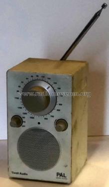
Ausführung: silber/weiß
Ausführung: silber/weiß

AF and power supply / charge

Ausführung: türkis/silber
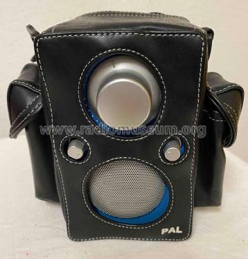
Umhängetasche für iPAL
Click on the schematic thumbnail to request the schematic as a free document.
- Main principle
- Superheterodyne (common); ZF/IF 10700/455 kHz
- Wave bands
- Broadcast (BC) and FM or UHF.
- Power type and voltage
- Storage Battery for all (e.g. for car radios and amateur radios) / 7.2 Volt
- Loudspeaker
- Permanent Magnet Dynamic (PDyn) Loudspeaker (moving coil) / Ø 2.5 inch = 6.4 cm
- Power out
- 3 W (unknown quality)
- Material
- Plastics (no bakelite or catalin)
- from Radiomuseum.org
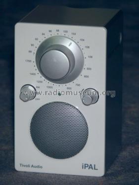
- Model: iPAL - Tivoli Audio; Cambridge, MA
- Shape
- Design Radio or Novelty / Gadget - fancy or unusual shape.
- Dimensions (WHD)
- 3.75 x 6.25 x 4 inch / 95 x 159 x 102 mm
- Notes
-
iPAL is a "marketing" version of PAL. It appeared latest 2004 (SFT test october 2004). Colour only white, fitting best to pluggable Apple IPOD being white as well. PAL is originally priced 130 USD, but PAL / iPAL sell up to 250 € in Europe.
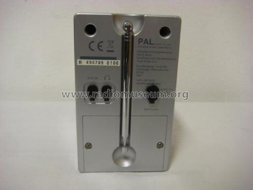
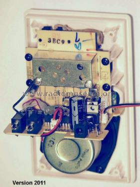
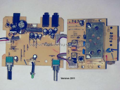
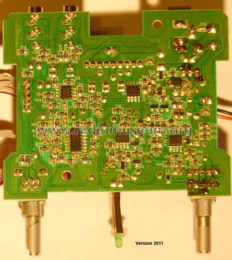
PAL and iPAL are technically identical and share the owner's manual. iPAL has a normal flat surface while PAL housing is rubber- clad. But tuner completely changed (before 2011) because of main receiver IC change ( early TEA5711T Philips, late LR1844 Sanyo). ICs ( iPAL, version 2011): MC 34074 (ONSEMI, 4x OP, sound), MC34072 (ONSEMI, 2x OP), BQ2002(Texas, charge management), LP2951 (Texas/ONSEMI, 5V voltage regulator), TDA7056B (NXP, AF power amp), LM358 (?, Texas, 2x OP, LED driver), LR1844 (Sanyo, AM/FM receiver) . iPAL has good reception and sound, but elder NiMH battery block will prevent radio from switching on.
Internal Nimh battery can be charged with plug-in 12 VDC external power source.
Neupreis 2008 in Deutschland 199 Euro.
- Net weight (2.2 lb = 1 kg)
- 0.9 kg / 1 lb 15.7 oz (1.982 lb)
- Price in first year of sale
- 249.00 Euro
- Author
- Model page created by Boris Witke † 9.2024. See "Data change" for further contributors.
- Other Models
-
Here you find 7 models, 7 with images and 3 with schematics for wireless sets etc. In French: TSF for Télégraphie sans fil.
All listed radios etc. from Tivoli Audio; Cambridge, MA
Collections
The model iPAL is part of the collections of the following members.
Forum contributions about this model: Tivoli Audio;: iPAL
Threads: 1 | Posts: 1
My iPAL, bought from a fleemarket, turned out to be defective. Soon I realized that the battery pack (7,2V NiMH, capacity about 1,6 Ah) was not in order, as it, even charged, didn´t supply enough current to power the radio. But this wasn´t the only flaw. Even with a suitable- though not original- AC/DC power adaptor my iPAL didn´t start. I had to learn that Tivoli doesn´t provide any service information about its radios. Luckily I found some detail schematics, taken from a older PAL per hand and Ohmmeter (which must have been a quite time- consuming job with all the minute SMD electronic parts). They were better than nothing, and after several corrections - compared to my own radio- , I put some of them here in RM.org. Please remember they are not originally from Tivoli, so some unlabelled or coded SMD parts are still unknown.
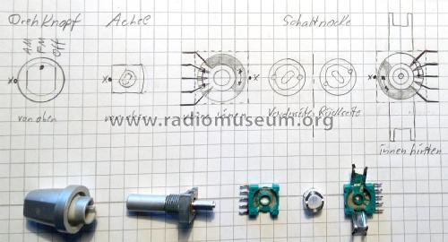
Taking the radio apart is impossible if the knobs fit so tight that they can´t be pulled off. They get thinner to the outer end, and so they are not easy to grasp. In this case, double-sided adhesive tape may help.
The main switch had very bad contacts. Facing a hard cleaning procedure, I decided to solder it out (10 contacts), clean, check and re-solder. That prevented the board from contact to the cleaner.
I found D2 to be defective (open), most probably due to overcurrent, so I changed both D1 and D2 (1N4002). The measurements at D3 were unclear, so I changed it as well against a fitting SMD silicon diode. Q4 (PNP) and Q2 (P-FET) were ok. Now the radio played, but only when I shorted Drain and Source from Q2 for a short moment. Grounding of Gate Q2 for a short time made iPAL play as well (so I found that Q2 was ok). Now the question was why the start-up circuitry (D7, Q3, Q2 and some more parts) didn´t work. Q3, surely an N-channel enhancement FET (BSS138 or similar) was ok. I assumed a runtime problem. When switched on, C16 puts a High-Pulse on Gate Q3, forcing it to switch on and followingly Q2. But when it takes a time to switch on the 5V tuner supply (Elko charge and so on) that is longer than the switch-on pulse through C16, powering up may fail, because the ERROR pin (pin 5 of the 5V regulator IC U4) will remain low, thus pulling down Gate Q3 again. My solution was to enlarge the switch-on pulse just by using a bigger cap for C16. I soldered a 1µF cap over C16, which is available in the same size, and now the radio switches on correctly.
I think that the effort was worth it. Compared to its small size, the radio has a full, warm sound, and its FM reception is really good. Thanks to the people behind "harrysradios.blogspot.com" that drew and published the first schematics.
Regards,
Boris Witke
Boris Witke † 9.2024, 13.Jul.17