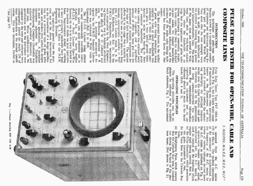
Pulse Echo Tester PET IOOA/B
TMC (Telephone Manufacturing Company); Sydney, NSW
- Pays
- Australie
- Fabricant / Marque
- TMC (Telephone Manufacturing Company); Sydney, NSW
- Année
- 1959
- Catégorie
- Appareils de mesure et de dépannage (matériel de labo)
- Radiomuseum.org ID
- 322411


Cliquez sur la vignette du schéma pour le demander en tant que document gratuit.
- No. de transistors
- Semi-conducteurs présents
- Semi-conducteurs
- Gammes d'ondes
- - sans
- Tension / type courant
- Alimentation Courant Alternatif (CA) / 240 Volt
- Haut-parleur
- - - Pas de sortie basse fréquence
- Matière
- Boitier métallique
- De Radiomuseum.org
- Modèle: Pulse Echo Tester PET IOOA/B - TMC Telephone Manufacturing
- Forme
- Modèle de table générique
- Remarques
-
The Pulse Echo Tester, Type PET IOOA/B was developed from a design specification from the PMG Research Laboratories for fault location, employing the pulse echo principle for the location of faults on telephone lines of relatively small bandwidths.
OPERATING PRINCIPLES
The operating principles may be explained by reference to the simplified block schematic, Fig. 2.
The instrument is operated from the A.C. mains. The (pulsed) operations of the instrument are synchronised to the frequency of the A.C. mains by means of various voltages derived from the A.C. mains as indicated on Fig. 2.
A square wave "master control" signal, synchronised with the A.C. mains, is used to control all the functions which require rigid timing control, that is:
- the Pulse Generator, which generates the pulse transmitted to line,
- the Time Base for the Cathode Ray Tube.
- the Brightening Pulse, which ensures that the Cathode Ray tube is blanked out during the fly-back of the electron beam. (Not shown in Fig. 2.)
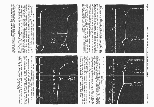
- the Marker Generator, which generates "marker. pips" (timing marks at intervals of 20 and I00 microseconds) on a second trace of the C.R.T. and enabling echo-times to be determined with a high degree of accuracy.
The trace on which the marker pips are displayed is separate from that on which the received echoes are displayed. The two traces are obtained by the "alternate trace" method, the necessary switching functions being carried out by transistors and controlled by voltages derived, from the A.C. mains. The gain of the receiving amplifier is suppressed during the time the marker trace is being drawn; the suppression is carried out by a transistor under the control of the A.C. mains.
- Littérature
- -- Original-techn. papers. (Telecommunication Journal of Australia Vol. 12, No 5 Oct 1960, Page 329.)
| Telecommunication Journal of Australia Vol. 12, No 5 Oct 1960, Pages 329 - 337. | 1645 KB |
- Documents sur ce modèle
- Auteur
- Modèle crée par Gary Cowans. Voir les propositions de modification pour les contributeurs supplémentaires.
- D'autres Modèles
-
Vous pourrez trouver sous ce lien 2 modèles d'appareils, 2 avec des images et 1 avec des schémas.
Tous les appareils de TMC (Telephone Manufacturing Company); Sydney, NSW