- País
- Gran Bretaña (GB)
- Fabricante / Marca
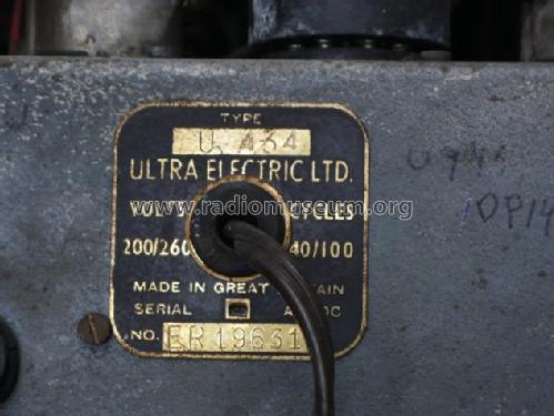
- Ultra Electric Ltd.; London
- Año
- 1947/1948
- Categoría
- Radio - o Sintonizador pasado WW2
- Radiomuseum.org ID
- 157698
-
- alternative name: Ultra Radio and Television
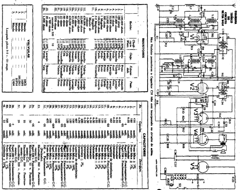
Service manual
Haga clic en la miniatura esquemática para solicitarlo como documento gratuito.
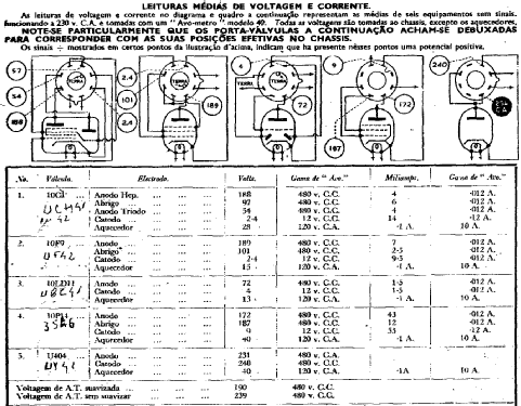
- Numero de valvulas
- 5
- Principio principal
- Superheterodino en general; ZF/IF 455 kHz
- Gama de ondas
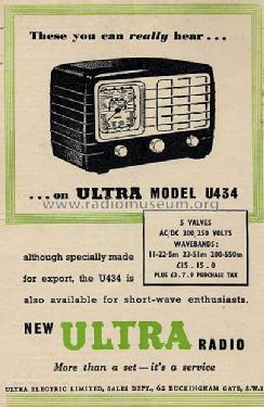
- OM y más de dos OC
- Tensión de funcionamiento
- Red: Aparato AC/DC. / 110-220 Volt
- Altavoz
- Ø 12.5 cm = 4.9 inch
- Potencia de salida
- 2 W (unknown quality)
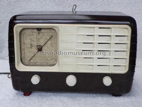
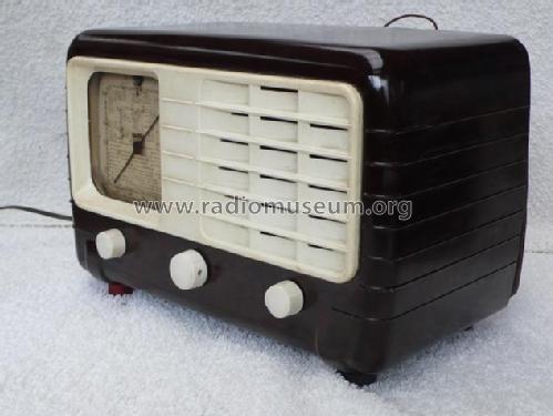
- Material
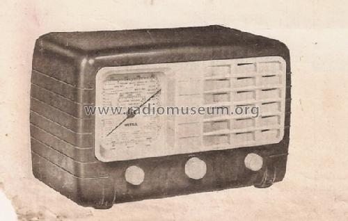
- Bakelita
- de Radiomuseum.org
- Modelo: U 434 - Ultra Electric Ltd.; London
- Ancho, altura, profundidad
- 300 x 150 x 188 mm / 11.8 x 5.9 x 7.4 inch
- Anotaciones
-
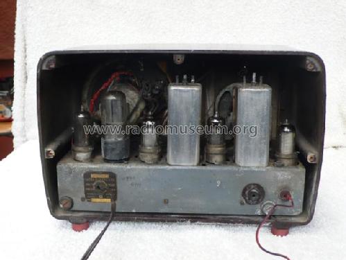
5-valve, 3-band AC/DC superhet.
See also Model U 431.
- Peso neto
- 4.7 kg / 10 lb 5.6 oz (10.352 lb)
- Procedencia de los datos
- - - Manufacturers Literature
- Referencia esquema
- La Documentation du Revendeur - Radio
- Documentación / Esquemas (1)
- -- Original-techn. papers.
- Autor
- Modelo creado por João Luis Mendes Colaço. Ver en "Modificar Ficha" los participantes posteriores.
- Otros modelos
-
Donde encontrará 235 modelos, 153 con imágenes y 149 con esquemas.
Ir al listado general de Ultra Electric Ltd.; London
Colecciones
El modelo es parte de las colecciones de los siguientes miembros.
Contribuciones en el Foro acerca de este modelo: Ultra Electric Ltd.;: U 434
Hilos: 1 | Mensajes: 9
Dear Radiophiles,
Can anyone help me to find the trouble I am having with my Ultra U434.It does not oscilate in any of the the bands on the half lower frequency,when the tunning capacitor is half rotated.The oscilator grid current apears at half rotation of tunning,R2,C10,R3,R4,C22 seem OK,Continuity and resistances of coils according to manufacturer´s specifications.Could it be that the use of a UCH 42 instead of a 10C1 should be the cause for this fault?And beeing so,what could be done to overcome this problem using the UCH42 once the 10C1 is not available here? Sugestions wellcome with thanks,A.B.Regada
Antonio Barros-Regada, 17.Dec.10