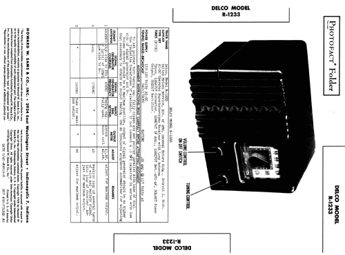
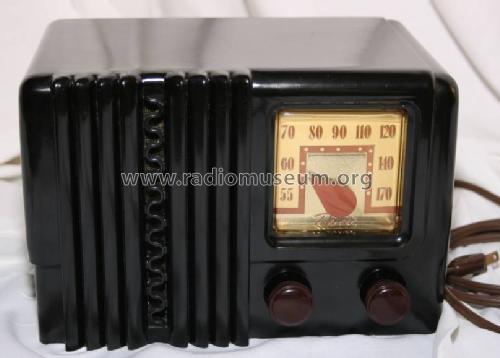
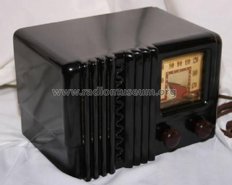
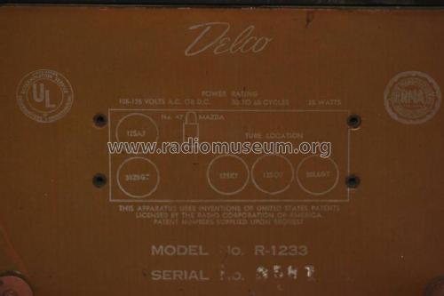
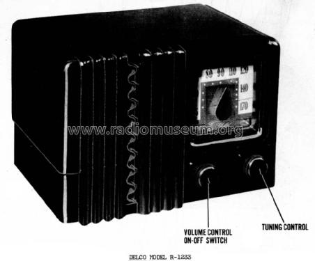
Delco R-1233
United Motors Service (Delco)
- Produttore / Marca
- United Motors Service (Delco)
- Anno
- 1948
- Categoria
- Radio (o sintonizzatore del dopoguerra WW2)
- Radiomuseum.org ID
- 64478
-
- alternative name: Delco Radio Corp. (Appliance) || Delco-Remy Division, General Motors Corp. || United Motors Service Delco General Motors
- Brand: Chieftain || Delco


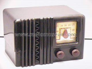
By courtesy of William Kendrick, USA
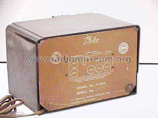
By courtesy of William Kendrick, USA

SAMS Photofact
Clicca sulla miniatura dello schema per richiederlo come documento gratuito.
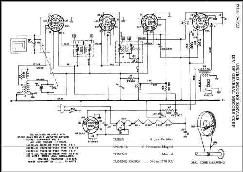
- Numero di tubi
- 5
- Principio generale
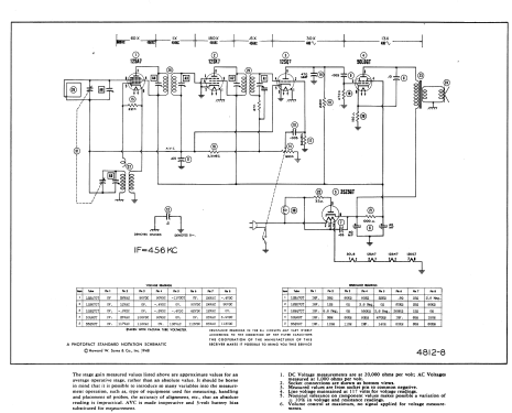
- Supereterodina (in generale); ZF/IF 456 kHz; 2 Stadi BF
- N. di circuiti accordati
- 6 Circuiti Mod. Amp. (AM)
- Gamme d'onda
- Solo onde medie (OM).
- Tensioni di funzionamento
- Alimentazione universale (doppia: CC/CA) / 110 - 120 Volt
- Altoparlante
- AP magnetodinamico (magnete permanente e bobina mobile) / Ø 5 inch = 12.7 cm
- Materiali
- Plastica (non bachelite o catalina)
- Radiomuseum.org
- Modello: Delco R-1233 - United Motors Service Delco
- Forma
- Soprammobile con qualsiasi forma (non saputo).
- Fonte esterna dei dati
- Ernst Erb
- Fonte dei dati
- The Radio Collector's Directory and Price Guide 1921 - 1965
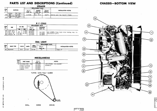
- Riferimenti schemi
- Rider's Perpetual, Volume 18 = 1949 and before
- Bibliografia
- Collector's Guide to Antique Radios 4. Edition
- Letteratura / Schemi (1)
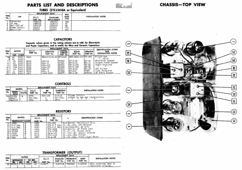
- Photofact Folder, Howard W. SAMS (Set 42, Date 7/48, Folder 4812-8)
- Altri modelli
-
In questo link sono elencati 585 modelli, di cui 341 con immagini e 548 con schemi.
Elenco delle radio e altri apparecchi della United Motors Service (Delco)
Collezioni
Il modello Delco R-1233 fa parte delle collezioni dei seguenti membri.
Discussioni nel forum su questo modello: United Motors: Delco R-1233
Argomenti: 1 | Articoli: 1
Fellow Radiophiles,
Have you ever seen a tube radio powering up?
Now, you can see this little AA5 Delco R1233 powering up on a Tektronix 575 Curve Tracer.
For a short video of this warm-up sequence, go to YouTube
(http://www.youtube.com/watch?v=WccCfSNpsuk)
This classic All-American-5 Tube radio from 1948 draws 28Watts of power after tube warm-up.
The Tektronix 575 Curve tracer from 1958 supplies power to the radio and shows applied voltage and drawn current in real time, during warm-up.
The Horizontal Axis shows the full-wave rectified 120VAC Voltage supplied voltage. Note the 160V peak on the right. The Vertical axis shows the resulting current.
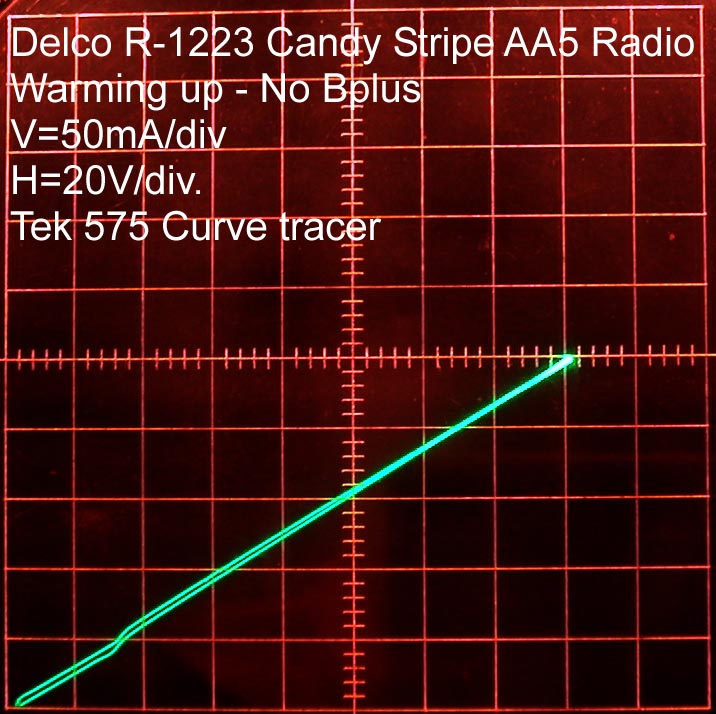
There is an initial surge of current that is off the scale. Then it settles down quickly, as the heaters (filaments) warm up as seen in this photo.
The heater current drops a little further after full warm-up, as the shallow portion of the next photo shows.

After a few seconds, these heaters have heated up the surrounding cathodes to start thermionic emission, and the 35Z5 power rectifier starts to draw current on the sine-wave peaks. After full warm-up, the curve shows a shallow portion where only heater current is drawn, and a steep portion, where rectified current for the internal high voltage is also drawn.
A simple extrapolation shows that at peak voltage, half the current is drawn by the heaters and the other half by the 35Z5 rectifier. The peak current on positive peaks is 400ma.
The radio only operates with the plug in one orientation with respect to the TEK575 sweep jacks, because the TEK575 supplies full wave rectified AC. This 120Hz power differs slightly from the usual 60Hz power in that the operating Bplus ripple will be reduced to half, and the Bplus voltage will be slightly higher than usual.
The TEK575 can only put out unipolar voltages as full wave rectified AC power. The TEK 576 can put out full AC power.
I dedicate this post and the YouTube video, which is my first, to analog visionary, guru and Linear Technology Staff Scientist Jim Williams.
It was Jim who, a few years ago, told me " Just throw it on the curve-tracer".
Regards,
-Joe
Joe Sousa, 11.Dec.09