Digital videotape controller 7500
Unknown - CUSTOM BUILT: Switzerland (CH)
- País
- Suiza
- Fabricante / Marca
- Unknown - CUSTOM BUILT: Switzerland (CH)
- Año
- 1972
- Categoría
- Signal Processing and Computing
- Radiomuseum.org ID
- 305610


Haga clic en la miniatura esquemática para solicitarlo como documento gratuito.
- Gama de ondas
- - no hay
- Tensión de funcionamiento
- Red: Corriente alterna (CA, Inglés = AC) / 220-240 Volt
- Altavoz
- - - No hay salida de sonido.
- de Radiomuseum.org
- Modelo: Digital videotape controller 7500 - Unknown - CUSTOM BUILT:
- Forma
- Formas varias descritas en notas aparte.
- Ancho, altura, profundidad
- 482 x 311 x 400 mm / 19 x 12.2 x 15.7 inch
- Anotaciones
-
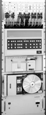
The 7500 controller was designed in 1972 to allow a 32K Hewlett-Packard 2100A minicomputer to control an IVC MMR-1 1-inch helical scan video recorder for the storage of digital data. The controller comprises 25 6U modules in a CAMAC crate, but with custom rear wiring instead of a standard CAMAC dataway. The controller is connected to the computer via 9 standard HP microcircuit interface cards, and includes the following modules as well as a separate 5v power supply:
Transport control unit.
Motion command output/transport status input.
Signal status, tachometer and address occupied input.
Performance monitor.
Function control unit.
Function commands output/error table input.
High density data verify unit.
Frequency counter, tape speed monitor and error totaliser.
High density read unit.
Fast data input/output unit (DMA).
High density write unit.
System timing generator.
Permanent address read (read/write head).
Read/write head write unit.
Read/write head read unit.
Status address read/write (read/write head).
Decimal data display.
Permanent address read (preview head).
Preview head read unit.
Status address read (preview head).
Binary data display.
Permanent address verify unit (read-after-write head).
Read-after-write head read unit.
Status address verify unit (read-after-write head).
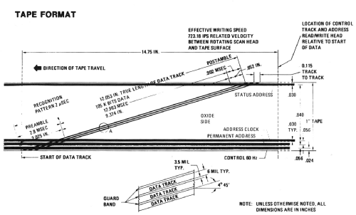
Power supply control unit.All timing signals for the MMR-1 are generated in the controller from a single 16.2 MHz quartz crystal. Low-density data modules control writing and reading on 4 longitudinal tracks at 3 fixed head stacks positioned in the tape path prior to the high-density scanner. The permanent addresses, which uniquely identify each high-density scanline in the physical data structure, and status information, which identifies their (time-varying) assignment in the logical data structure, are recorded as 22-bit words (plus 2 checkbits) separated by inter-record gaps. They can be read bidirectionally at the preview and verify head stacks at synchronous speed, and at the read/write head at a search speed that can be controlled by the computer from 17.6 cm/sec to 10.2 m/sec. Scanlines are 'skipped' (i.e., left unrecorded or unread) as necessary to match the data rates during any writing or reading tape pass, the skipped scanlines being utilised on subsequent passes.
RZ recording is used for the control track and NRZ1 for the permanent addresses; while the status track, which is located at the top edge of the tape where it intersects only the scanline postamble, is recorded biphase mark. The separation between each status record and the scanline with which it is associated is chosen such that the status is between the preview and read/write heads when the corresponding high-density data are scanned. Hence it is possible to make a high-density read or write decision on the basis of the status read at the preview head, and to update the status information at the read/write head by the data read from the scanline. The high-density data are recorded at 441 b/mm (11,200 bpi) by Miller coding. After a preamble traversing the region of intersection with the lower longitudinal tracks, a unique recognition pattern is recorded and immediately followed by computer data in the following 23.56 cm of the scanline. With a recording density of 1.6 x 10⁵ b/cm2 (106 b/in2), each videotape cartridge had a capacity equivalent to that of several hundred conventional computer magnetic tape reels.
The videotape controller was designed by Bruce Taylor. A switching system was also built for interfacing two MMR-1 recorders with two HP2100A computers, allowing either recorder to be connected to either computer.
- Peso neto
- 18 kg / 39 lb 10.4 oz (39.648 lb)
- Autor
- Modelo creado por Bruce Taylor. Ver en "Modificar Ficha" los participantes posteriores.
- Otros modelos
-
Donde encontrará 32 modelos, 30 con imágenes y 3 con esquemas.
Ir al listado general de Unknown - CUSTOM BUILT: Switzerland (CH)
Colecciones
El modelo Digital videotape controller es parte de las colecciones de los siguientes miembros.