Supradyna Far 4 Lampi
Unknown - CUSTOM BUILT: Romania (RO)
- Paese
- Romania
- Produttore / Marca
- Unknown - CUSTOM BUILT: Romania (RO)
- Anno
- 1930 ??
- Categoria
- Kit, scatola di montaggio (parti sfuse e istruzioni o solo istruzioni di montaggio)
- Radiomuseum.org ID
- 287566


Clicca sulla miniatura dello schema per richiederlo come documento gratuito.
- Numero di tubi
- 4
- Valvole
- A441N_5pin A442 A415 B443_4pin
- Principio generale
- Supereterodina (in generale); ZF/IF 56,6 kHz; 1 Stadi BF
- N. di circuiti accordati
- 3 Circuiti Mod. Amp. (AM)
- Gamme d'onda
- Onde medie (OM) e onde lunghe (OL).
- Tensioni di funzionamento
- Batterie (di accumulatori e/o a secco) / 4 & 40 & 60 & 150 & negative bias Volt
- Altoparlante
- - Questo apparecchio richiede altoparlante/i esterno/i.
- Radiomuseum.org
- Modello: Supradyna Far 4 Lampi - Unknown - CUSTOM BUILT:
- Dimensioni (LxAxP)
- 400 x 200 x 220 mm / 15.7 x 7.9 x 8.7 inch
- Annotazioni
-
Kit assembly instructions for a superheterodyne receiver "Supradyna FAR" with 4 tubes, using components of the French company FAR.
The set can be operated with the following tube alternatives:
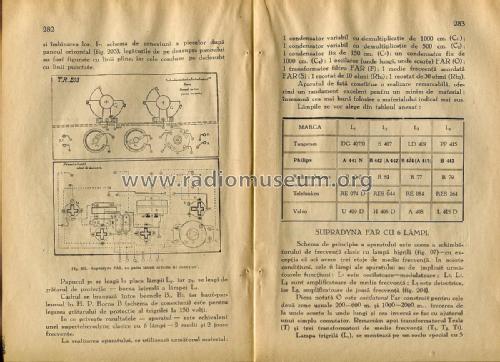
- Tungsram: DG407/0, S407, LD409
- Philips: A441N, B442 or A442, B424 or A415, B443
- La Radiotechnique: R43/0, R81, R77, R79
- Telefunken: RE074D, RES044, RE084, RES164
- Valvo: U409D, H406D, A408, L415D
Published in the book "All Secrets of Radiophony" by Ing. Florea, Bucharest 1930.
- Letteratura / Schemi (1)
- Ing. I. C. Florea, "Toate Tainele Radiofoniei", p.280-283
- Autore
- Modello inviato da Pitagora-Petru Schorsch. Utilizzare "Proponi modifica" per inviare ulteriori dati.
- Altri modelli
-
In questo link sono elencati 3 modelli, di cui 3 con immagini e 1 con schemi.
Elenco delle radio e altri apparecchi della Unknown - CUSTOM BUILT: Romania (RO)
Collezioni
Il modello Supradyna Far 4 Lampi fa parte delle collezioni dei seguenti membri.
Discussioni nel forum su questo modello: Unknown - CUSTOM: Supradyna Far 4 Lampi
Argomenti: 1 | Articoli: 1
HOW TO ASSEMBLE THE FAR “SUPRADYNE” WITH FOUR VALVES
The circuit diagram is shown in Fig. 201:
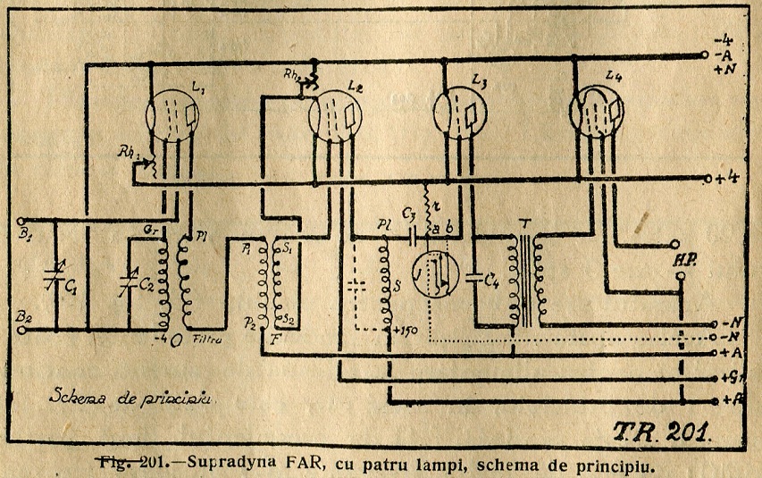
The two-grid valve, L1 connected in the classical way is performing the frequency conversion. The special feature of the set consists in the only screen-grid valve L2 which amplifies the intermediate frequency. In the heater circuit of this valve we notice a rheostat Rh2. Its function could be better understood reading the considerations made in §51. We stated there, that the inner resistivity of a screen–grid valve being greater than the inner resistivity of the normal triode, the stages equipped with such valves would have an increased selectivity. It is also known that the inner resistivity of any valve could be increased by reducing its heating. So, the set’s selectivity could be adjusted between certain limits by adequately adjusting the Rh2 rheostat. Diminishing exaggeratedly the heating current will bring the valve out of its normal function range.
In other super-heterodyne sets the return of the control grid circuit of the intermediate frequency amplifier is connected to a 400 Ohm potentiometer which adjusts the negative grid bias. Here, such potentiometer would only complicate the diagram, and represent a useless waste of money. Screen grid valves needing low voltages for grid bias (see § 51) the return of the control grid could be connected before the rheostat, directly on the heater pin, as shown in the circuit diagram. This configuration, brings also, among adequately grid biasing, the possibility of controlling the selectivity - as explained above.
The plate of the screen-grid tube is connected to a tank circuit (S) tuned to the intermediate frequency. From here the signal reaches the detector stage.
The “FAR” kit manufacturers have chosen the 5300 m wavelength for the intermediate frequency – satisfying two conditions: the one we spoke about when studying the screen grid tubes, and the second that we mentioned in § 55 discussing frequency conversion.
We generally stated there, that, intermediate frequency, has to be chosen in the range of 4500 – 5500 m. wavelength. On the other hand, from analysing the screen-grid tubes curves from fig. 86, results that we should choose a wavelength towards the upper limit of this interval.

The electric gramophone amateurs could equip this radio set with an input jack connected between a, and b, as shown in fig. 201 with dotted lines.
The building of the set could be easily done following the given plans. Fig. 202 shows the mounting panels and the way they are fitted together:

The connections above the panel in the wiring diagram of the horizontal panel (fig. 203) are drawn with full lines and those underneath with dotted lines:
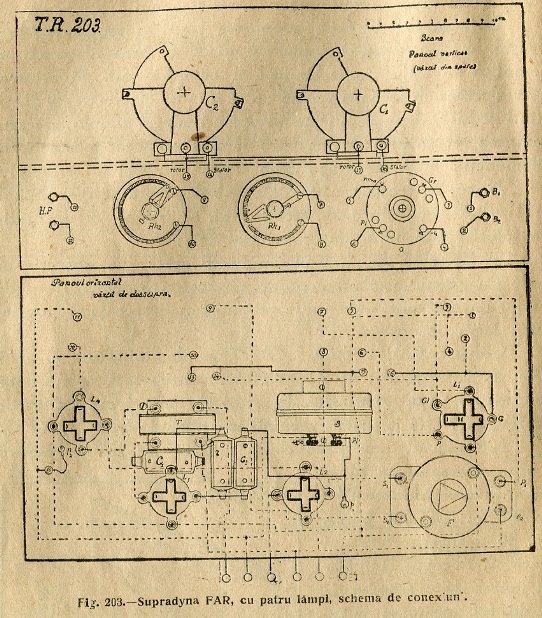
The terminal p1 is used to connect the rest of the circuit to the plate of the L2 (on top of the valve) and p2, to the screen grid of L4 (the side binding post on the tube mounting). The loop antenna should be connected between B1 and B2 and the loudspeaker between the binding posts marked H.P. The B banana socket (see wiring diagram) is used to connect through terminal p2 the screen grid of the final pentode to +150 volts.
The performance of the set equals a classic super-heterodyne with 6 tubes – two intermediate and two low frequency stages.
To build the set, following components are needed:
1 variable capacitor 1000 cm. (C1) with slow motion dial drive;
1 variable capacitor 500 cm. (C2) with slow motion dial drive;
1 capacitor 150 cm. (C3);
1 capacitor 1000 cm. (C4);
1 FAR oscillator unit (Long Waves & Short [Medium] Waves) (O);
1 FAR intermediate frequency filter (F);
1 FAR intermediate frequency tank circuit (S);
1 rheostat 10 Ω (Rh1);
1 rheostat 30 Ω (Rh2).
The valves are to be chosen according to the following table:

This radio set provides a remarkable performance for a minimum of components. It represents the best employment of the above listed material.
****
Allegati
- FAR_SUPRADYNE4_sch (251 KB)
- FAR_SUPRADYNE4_Fig86 (253 KB)
- FAR_SUPRADYNE4_Panels (294 KB)
- FAR_SUPRADYNE4_Wiring (196 KB)
- FAR_SUPRADYNE4_VALVES (229 KB)
Pitagora-Petru Schorsch, 25.Jan.17