Chisholm Model 369
Vancouver Radio or Chisholm Industries; Vancouver
- Land
- Kanada
- Hersteller / Marke
- Vancouver Radio or Chisholm Industries; Vancouver
- Jahr
- 1950 ?
- Kategorie
- Rundfunkempfänger (Radio - oder Tuner nach WW2)
- Radiomuseum.org ID
- 359249


Klicken Sie auf den Schaltplanausschnitt, um diesen kostenlos als Dokument anzufordern.
- Anzahl Röhren
- 5
- Hauptprinzip
- Superhet allgemein; ZF/IF 455 kHz
- Anzahl Kreise
- 6 Kreis(e) AM
- Wellenbereiche
- Mittelwelle, keine anderen.
- Betriebsart / Volt
- Wechselstromspeisung / 110 Volt
- Lautsprecher
- Dynamischer LS, keine Erregerspule (permanentdynamisch) / Ø 6 inch = 15.2 cm
- Material
- Gerät mit Holzgehäuse
- von Radiomuseum.org
- Modell: Chisholm Model 369 - Vancouver Radio or Chisholm
- Form
- Tischmodell, Zusatz nicht bekannt - allgemein.
- Abmessungen (BHT)
- 20.25 x 9.5 x 10.25 inch / 514 x 241 x 260 mm
- Bemerkung
-
This Chisholm Model 369 radio was very difficult if not impossible to find specific documentation of any sort. The above information has come from the radio and a Chisholm Model 540 & 530 schematic and service information.
- Nettogewicht
- 20.25 lb (20 lb 4 oz) / 9.194 kg
- Autor
- Modellseite von Bruce Morgenstern angelegt. Siehe bei "Änderungsvorschlag" für weitere Mitarbeit.
- Weitere Modelle
-
Hier finden Sie 8 Modelle, davon 7 mit Bildern und 1 mit Schaltbildern.
Alle gelisteten Radios usw. von Vancouver Radio or Chisholm Industries; Vancouver
Sammlungen
Das Modell Chisholm Model 369 befindet sich in den Sammlungen folgender Mitglieder.
Forumsbeiträge zum Modell: Vancouver Radio or: Chisholm Model 369
Threads: 1 | Posts: 1
The story behind the restoration of the Chisholm Model 369 Radio
This article is about how I came to own the Chisholm Model 369 radio and how it was almost stripped down for useable parts and the remainder was to go to the garbage.
Prelude:
The Chisholm Model 369 radio was given to me several 
years ago by a tube collector friend who lives near
Wenatchee in Washington State. He buys and sells
mainly tubes and sometimes gets radios and other radio
related items. He contacted me with pictures of this
radio and wondered if I would like it as it was Canadian
made.
I looked at the pictures and thought, it sure is in pretty
rough shape. The chassis was just placed in the cabinet,
the knobs and other miscellaneous bits, pieces and 
parts were all in a package. But it was free so I
graciously accepted it and put it with my stash of
radios for repair and restoration.
Restoration or disposal:
In 2020, I started a cleanup as I needed more storage room for new acquisitions. The radio’s that appeared to be beyond restoration I striped down and threw away what I thought was not useable. I came to this Chisholm model 369 radio which I had never heard of and thought before condemning it I should look up some information about the company and radio. I put a request on the Canadian Vintage Radio Society (CVRS) site to see if anyone could help me obtain a manual or schematic for this radio. Gary Kuster, replied and pointed me in the direction of an article written by, Gerald Taylor & Gerry O’Hara, on Chisholm Industries Limited. This article can be viewed using the following link. "Chisholm Link" It is a very in depth article with multiple pictures
about the Chisholm Family and Chisholm Industries Ltd. In 1939 Chisholm Industries was located on Main Street in Vancouver and then moved in 1955 to a 56,000 square foot facility in Port Moody. The original article also had links, which are non reachable today, to four separate Chisholm radios with schematics and other information for each. None were for the model 369 the only one that was close was for a Chisholm model 540. I downloaded it, looked it over, and the decision was made to start the restoration.
Inspecting the chassis:
This restoration will show some of the difficulties encountered when one cannot obtain a service manual, schematic or any other specific information on a radio, when tubes in their sockets do not match the tubes indicated on the cabinet label and to make matters worse when someone has done some major work and modifications to the circuitry.
Checking the underneath of the chassis, everything seemed to look copacetic even though there was some major work done that looked very crude and unprofessional.
 Tube Checking:
Checking the tubes I found that the 5Y4G and the 6K6GT were completely dead. All all the others checked just fine so I replaced the two dead tubes. On the inside wall of the cabinet was a label showing the tube layout and tube numbers. The only difference between what was on the label and in the chassis was the label shows a 6SK7 and the chassis has a 6K7 installed. There is not a direct substitution between a 6SK7 and a 6K7. The 6K7 has a grid cap on the top and the 6SK7 does not. This is the first tube discrepancy I found.
Checking the underneath of the chassis, everything seemed to look copacetic even though there was some major work done that looked very crude and unprofessional.
Power to the Chassis:
I hooked the power to the chassis through a Variac, slowly increasing the voltage and pausing as I increased it. I was up to approximately 100 volts and was looking at something else for a moment and when I looked back there was smoke billowing from all the holes in the chassis near the transformer. It was an awe-inspiring sight. As fast as I could I turned the Variac off. I was hoping that maybe a resistor or some small component had gone up in smoke. Not to be. I turned the chassis over and there was still smoke coming out of the bottom of the transformer where the leads come out and the transformer was very hot. I was really hoping that the transformer did not “Thermally Reconfigure” melt.
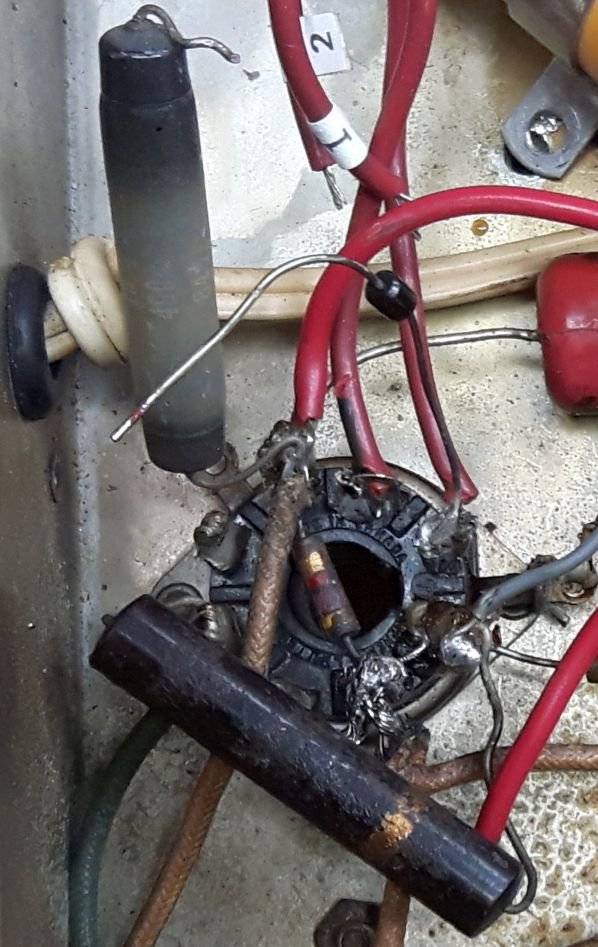
Damage observation and cause of the smoke:
It was obvious that at some point in time the power transformer had been replaced. I started to check out the wiring and was a little overwhelmed at what I observed. It looked like most of the original wiring going to the 5Y4 had been cut off as well as other components such as resistors and capacitors were also cut off and moved. Where the wires were cut off the terminals the ends of the wires were not removed from the socket terminals. The new wiring from the replacement transformer as well as other components were just soldered on top of the old wiring on the terminals. In the long run leaving the ends of the wire in place was very helpful.
Replacement Transformer:
The replacement transformer that went up in smoke was wired to the 5Y4 as follows: the two high voltage “B+” wires were connected to filament terminal #7 and filament terminal #8.
The center tap went to pin #1 which was used as a ground. As there was only one filament winding from the transformer of 6.3 volts, it was connected to Pin #5 Plate and Pin #2 that was soldered together with pin #1 as a ground connection.
 Now I get the manual out that I downloaded for the model 540. The schematic shows a 5Y3G as its rectifier. My 369 cabinet label shows a 5Y4 and the unit had a 5Y4 in it that was dead. Before I powered up the chassis I had replaced the 5Y4. There were some other obvious differences between the 540 manual and my model 369. The chassis component placement in the manual shows the transformer was moved, a choke was added, there were two oscillator trimmers on the RH side of the chassis, and there were four user controls on the front; Tuning-Phono-Volume-Tone, on/off. Mine has three user controls.
What am I going to do?
I decided to replace the complete power supply with new parts. I ordered a new Hammond transformer and choke to match as close as possible to the specifications in the model 540 downloaded manual. The specifications showed 280 volts on pin #2 of the 5Y3 and the closest transformer had a voltage of 600 volts center tapped. All the other parts I had in my stash.
The Transformer and choke were ordered from Mouser Electronics, who have an office and web site in Kitchener Ontario, but ship out of Mansfield Texas. I ordered this on Friday, October 23 and it was delivered to my door Tuesday October 27th. It was unbelievable! The other thing that amazed me was both the transformer and choke were manufactured in Canada by the Hammond manufacturing Co. Ltd, Waterloo, Ontario. It is not too often we see that.
The above parts were installed with two new filter capacitors and the output voltage was reduced with some series five watt resistors to the values given in the manual. All the other disconnected and cut off wires had to be traced to find out where they went and what their purpose was. As the on/off tone control switch did not work I took it apart, repaired and cleaned it as well as doing the same for the volume control.


 Powering up:
At this time I thought it was time to put power to the chassis. I connected it to the Variac and slowly turned the power up and watched the newly installed combination voltage / ammeter.
Both were looking just great. At 117 volts, specified in the manual, it was drawing .4 amps 48 watts. The chassis information plate showed the radio should draw 60 watts at 117 volts. It was well below the specified wattage. I turned the volume control up and waited a minute or so to see if there was any hum or hissing from the speaker but there was nothing. I rotated the tuning capacitor around to where I thought the AM station should be and it came in loud and clear. I was really pleased as it played very nicely, and the tone was great.
Remaining endeavors:
The following was not really technical. I had to find a tuning indicator that was missing and also restring it. Matching knob(s) had to be found that would match the two that came with the radio, I found a set of new knobs that I had ordered for another radio which I did not need and they correctly matched the existing ones. The speaker had to be remounted as it was just hanging loosely with one bolt, it sounds easy, but mounting it correctly so it would match up with the hole in the cabinet became quite time consuming. The speaker cloth was all tattered and torn so it also had to be replaced.
Refinishing the cabinet:
Refinishing is not really my forte even though I have done it in the past with good results. I have a friend, who is retired, and really enjoys the challenges involved in refinishing old cabinets. When I took him the cabinet I thought he would turn it down, but no, he was really enthused to get started. Thank you, Herb.
Now that the chassis and and cabinet are finished and the speaker cloth installed they can be married together.

Irony of it all
Before I started writing this article, I thought maybe I would sit down, download the 540 manual on my tablet and read it more closely. I thought I had completely read the manual as I was working on the radio. Here is what I found on a single page, all by itself. I got up and looked at all my paper work that I was using while restoring the radio and this page was not there.
This message was on one single page.
------------------------------------------------------------------------------------------------------
C H I S H O L M I N D U S T R I E S L T D .
Service Notes
Revision: Early series used 5Y4G and 6SK7
Tubes (not interchangeable without
Change in socket connections.)
Model 540
-----------------------------------------------------------------------------------------------------
Bruce Morgenstern
Bruce Morgenstern, 31.Jan.25