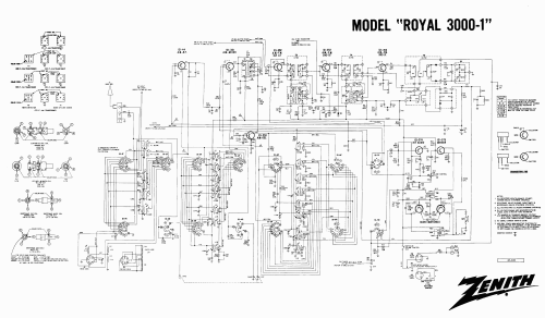
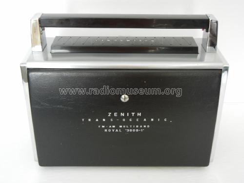
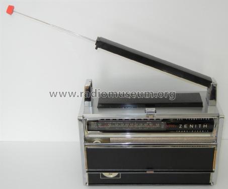
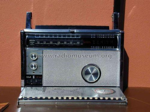
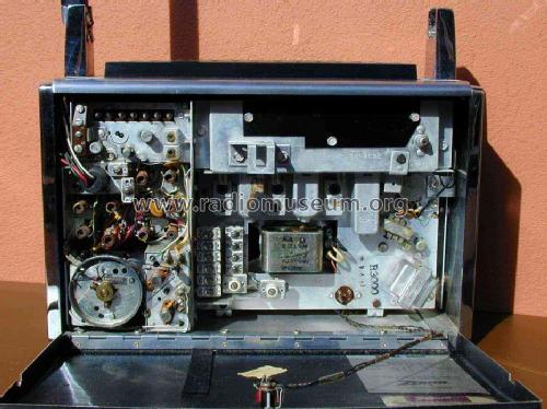
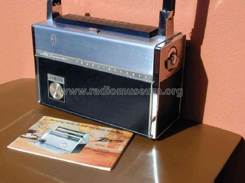
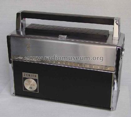
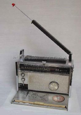
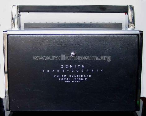
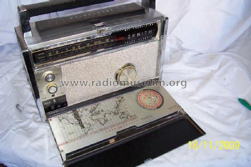
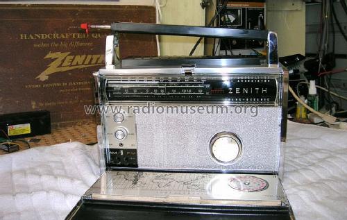
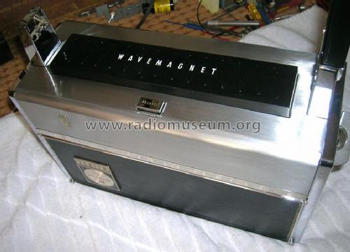
Trans-Oceanic (TransOceanic) Royal 3000-1 Ch= 12KT40Z3 or 12KT40Z8
Zenith Radio Corp.; Chicago, IL
- Pays
- Etats-Unis
- Fabricant / Marque
- Zenith Radio Corp.; Chicago, IL
- Année
- 1962–1971
- Catégorie
- Radio - ou tuner d'après la guerre 1939-45
- Radiomuseum.org ID
- 68765
-
- alternative name: Chicago Radio Lab


Ebay User nuvista48 Item 120892538983

Ebay User nuvista48 Item 120892538983
Ebay User nuvista48 Item 120892538983
Ebay User nuvista48 Item 120892538983
Ebay User nuvista48 Item 120892538983
Ebay User nuvista48 Item 120892538983
Ebay User nuvista48 Item 120892538983
Ebay User nuvista48 Item 120892538983
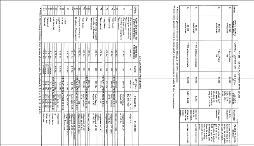
Cliquez sur la vignette du schéma pour le demander en tant que document gratuit.
- No. de transistors
- 12
- Principe général
- Super hétérodyne avec étage HF
- Gammes d'ondes
- PO, GO, OC et FM
- Tension / type courant
- Batteries / Alim. BT séparée avec fiche / D: 8 x 1.5 & 1 x 1.5 (dial light)/ 12 Volt
- Haut-parleur
- HP dynamique oval à aimant permanent
- Matière
- Matériaux divers
- De Radiomuseum.org
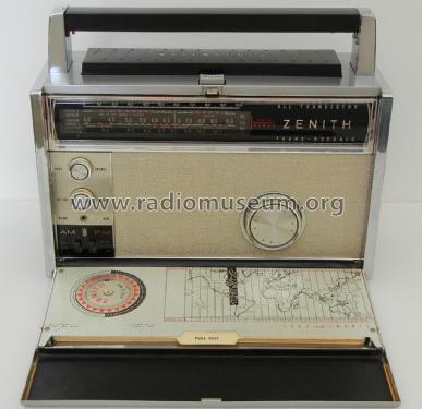
- Modèle: Trans-Oceanic Royal 3000-1 Ch= 12KT40Z3 or 12KT40Z8 - Zenith Radio Corp.; Chicago,
- Forme
- Portative > 20 cm (sans nécessité secteur)
- Dimensions (LHP)
- 12.6 x 10.5 x 5.2 inch / 320 x 267 x 132 mm
- Remarques
-
BC/LW/6xSW/FM; input port for external 12V power supply. See also the article here.
Siehe auch den Artikel hier.
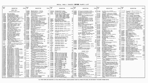
Si veda anche l'articolo in questa pagina.The Zenith transistor numbers read :
121-44,121-48,121-49,121-295,121-294,121-137,121-138,121-139,121-64,121-46,121-47,
121-47.
Features PM elliptical 4" x 6" speaker.
- Poids net
- 5.9 kg / 12 lb 15.9 oz (12.996 lb)
- Prix de mise sur le marché
- 275.00 $
- Source extérieure
- Bryant/Cones
- Source
- Zenith Transistor Radios
- Littérature
- Bryant & Cones: The Zenith TransOceanics
- Auteur
- Modèle crée par Konrad Birkner † 12.08.2014. Voir les propositions de modification pour les contributeurs supplémentaires.
- D'autres Modèles
-
Vous pourrez trouver sous ce lien 4519 modèles d'appareils, 4111 avec des images et 3656 avec des schémas.
Tous les appareils de Zenith Radio Corp.; Chicago, IL
Collections
Le modèle Trans-Oceanic (TransOceanic) Royal 3000-1 fait partie des collections des membres suivants.
- Edward Appel (USA)
- Howard Craven (GB)
- William Fague (CH)
- Renato Nestor Fernandez (RA)
- Massimo Follaro (I)
- Werner Gertsch (CH)
- Michael Gnaedig-Fischer (MEX)
- Christophe Howald (CH)
- Kent Johansson (S)
- Vladimir Manannikov (RUS)
- João Luis Mendes Colaço (P)
- Roberto Montalto (I)
- Rodolfo Gaston Wenceslao Nasasta (RA)
- Manuel Albano Neves (P)
- Jean Claude Pigeon † 2008 (F)
- Jaroslav Pochyly (CZ)
- Siegfried Raedel (D)
- Patrice Schoser (F)
- Sándor Selyem-Tóth (H)
- Serioja Tatu (CDN)
- Dirson Willig (BR)
Musées
Le modèle Trans-Oceanic (TransOceanic) Royal 3000-1 peut être vu dans les musées suivants.
Contributions du forum pour ce modèle: Zenith Radio Corp.;: Trans-Oceanic Royal 3000-1 Ch= 12KT40Z3 or 12KT40Z8
Discussions: 3 | Publications: 3
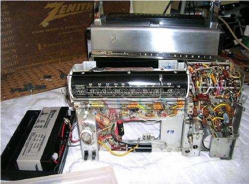
The Zenith Royal 3000 is noted for two things - one of the first FM portables (with low performance) and weak, tinny, rattly, sound. I recently got one that sounded so poor I figured I had nothing to lose by trying to fix it, with whatever extreme measures I needed.
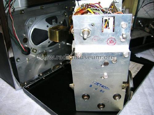
This one is a 3000-1. Side by side with the Royal 7000, or a tube Transoceanic, it sounded very weak, with no bass to speak of, and an annoying buzz/rattle at even low volumes. The basic audio circuit and speaker is not a lot different than the 7000, so it must be something straightforward. It was close to unlistenable. Being primarily a hi-fi person, not necessarily a radio guy, I expected that if I tightened everything up, and ensured that the cabinet was well-damped, that would help. Most of the rattles seemed to be coming from the front of the radio, but pressing on the grill metal, the pane; around the controls, or the dial cover helped very slightly, but not very much. So I disassembled the entire radio. I removed the chassis and connected the speaker with jumpers, and it was still rattling/buzzing severely on loud sounds, which eliminated the chassis as part of the rattling. I continued digging, to the point I had the case entirely apart. The sides and top were solid. The bottom and front are one piece, and the grill and speaker are attached to the front, very thin, aluminum parts. Tapping on these generated the rattles.
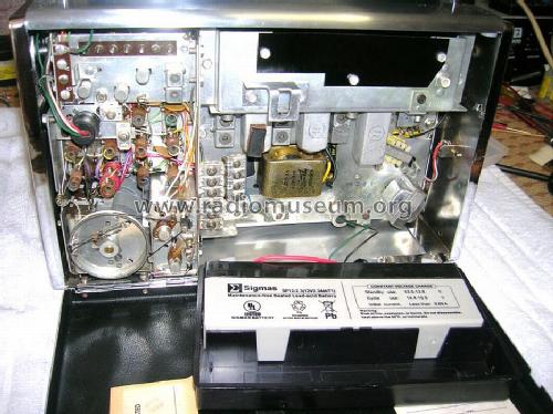
It was clear from some examination that the issue was probably the grill and the plastic trim panel rattling. One big problem - the plastic trim pieces and the speaker are held in with spring clips on studs that protrude through the grill material. There's basically no good way of removing these without breaking something. So thats what I did - I pried up the spring clips, and on all the plastic parts, the studs broke. I also remove the speaker, which is on riveted aluminum studs. The clips came off without breaking anything but the clips were hopelessly damaged. With the trim panel (under the knobs), the trim strip along the bottom of the grill, and the trim plate behind the tuning knob removed, the metal grill was free. Underneath the grill is a piece of cardboard or very thick "fish paper", and that goes up against the front panel. A few taps indicated that this was the problem, it was loose over most of the surface. Two little strips of double-sided tape were intended to keep the carboard up against the front panel, but had long since let go.
To correct this, I used spray contact cement (3m77, although 3m #90 might be better) on the back of the grill and the front of the cardboard spacer, let it dry, then stuck them together. Immediately this seemed much more solid than before and when tapped, went "thud" instead of "ping", indicated good damping of vibration. I then lightly glued (one side only) the grill and spacer to the front panel. It *might* be possible to removed the grill in the future at this bond line, but there's no way that the cardboard is coming off again without destroying it. I mounted the speaker back on the studs using silicone bathtub caulk on the paper standoff around the front of the speaker, and high-strength hot-melt glue on the studs. I then heated up the glue with a soldering iron and pressed the spring clips back on as best as I could. Then I glued the trim panel and trim strip back on with more high-strength hot melt glue. During reassembly, I replaced the dial cover with clear silicone caulk top and bottom to make sure it is solidly attached (instead of rattling around semi-loose on more spring clips).
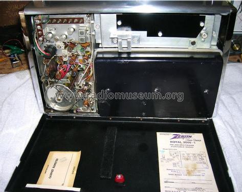
Finished reassembly, and, wow, it's REALLY fixed! Sounds at least as good as my Royal 7000 or 8G005, much more powerful sounding and can be cranked up until it's obviously clipping with very little rattling. The few that are left are in the antenna release lever and antenna tip, when the antenna is stowed. But it's dramatically better, just about as good as any small AM radio, much better than most. I have never heard any Royal 1000/3000 anything like it.
It's pretty easy to do and you just have to have the courage to undertake it. It took me a few evenings of work but it was well worth it.
Brett Buck, 04.Jun.11
Das Modell hatte vor Monaten noch funktioniert, nun war voll aufgedreht nichts mehr zu hören.
Edit 01.01.2011:
- AF126 russische Produktion unklar -> entfernt, siehe dieser Beitrag
- Fehler im Betreff korrigiert
- GF147 hinzu
Edit 02.01.2011:
- Weitere EIA Typen für NF-Vorstufen ergänzt
Marc Gianella, 29.Dec.10
Danke für das Lesen und evt. Antworten.
Werner Kassenbrock
Werner Kassenbrock, 28.May.05