- Country
- Germany
- Manufacturer / Brand
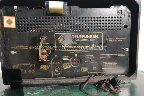
- Telefunken Deutschland (TFK), (Gesellschaft für drahtlose Telegraphie Telefunken mbH
- Year
- 1958/1959

- Category
- Broadcast Receiver - or past WW2 Tuner
- Radiomuseum.org ID
- 111175
Click on the schematic thumbnail to request the schematic as a free document.
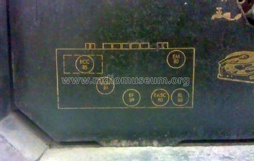
- Number of Tubes
- 6
- Main principle
- Superheterodyne (common); ZF/IF 460 kHz; 2 AF stage(s)
- Tuned circuits
- 6 AM circuit(s) 10 FM circuit(s)
- Wave bands
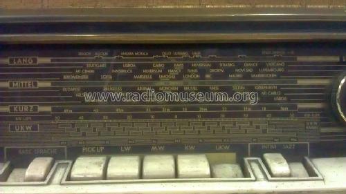
- Broadcast, Long Wave, Short Wave plus FM or UHF.
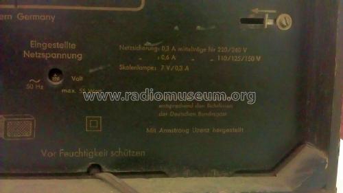
- Power type and voltage
- Alternating Current supply (AC) / 110, 125, 150, 220, 240 Volt
- Loudspeaker
- 3 Loudspeakers
- Power out
- 4 W (unknown quality)
- Material
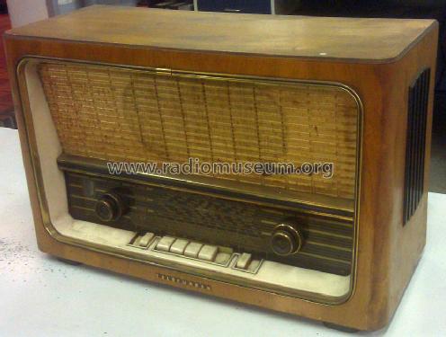
- Wooden case
- from Radiomuseum.org
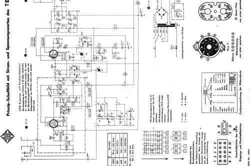
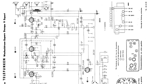
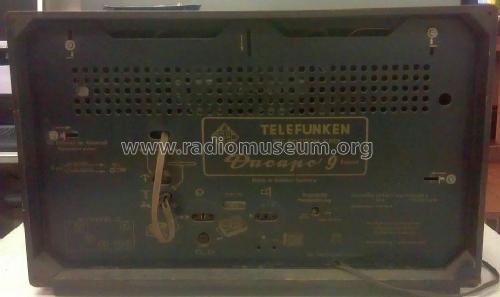
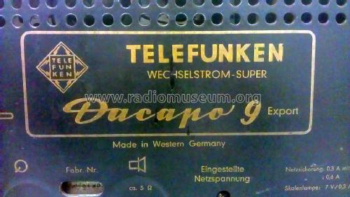
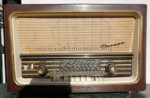
- Model: Dacapo 9 [Export] - Telefunken Deutschland TFK,
- Shape
- Tablemodel with Push Buttons.
- Dimensions (WHD)
- 540 x 340 x 230 mm / 21.3 x 13.4 x 9.1 inch
- Notes
-
Exportversion mit KW zusätzlich. Hier finden Sie die ganze Familie: Dacapo 9 Stereo, Dacapo 9 Export, Dacapo 9 in Nussbaum hell und Dacapo 9 dunkel.
- Net weight (2.2 lb = 1 kg)
- 8.5 kg / 18 lb 11.6 oz (18.722 lb)
- Source of data
- -- Original-techn. papers.
- Author
- Model page created by Walter Groer. See "Data change" for further contributors.
- Other Models
-
Here you find 3547 models, 3126 with images and 2095 with schematics for wireless sets etc. In French: TSF for Télégraphie sans fil.
All listed radios etc. from Telefunken Deutschland (TFK), (Gesellschaft für drahtlose Telegraphie Telefunken mbH
Forum contributions about this model: Telefunken: Dacapo 9
Threads: 1 | Posts: 2
Has anyone replaced the ratio detector electrolytic on this model? It appears to be contained within a screening can surrounding the EABC valve and containing the demodulator inductors. Does the top of the can lift off without desoldering everything from below? Is it acceptable to leave this original component and simply replace the accessible electrolytics?
Thank you.
Steve Browne, 15.Aug.12