
EL84

|
Variants
|
|||||||||||||||||||||||||||||||||||||||||||


|
Hits: 5143 Replies: 9
Reading tube pin datasheets
|
|
|
Mark Pennington
12.Apr.21 |
1
This is a beginners question. I understand the concept behind the simple testing of tubes for connectivity with a multimeter, but I don't understand how to check my results to a datasheet. For example, with the EL84 I understand that pins 4 and 5, the filament pins, should have connectivity and can see that they are shown as connected in the pin diagram. I know from experience that pins 1 and 2 also have connectivity. How is that connectivity shown in a tube pin diagram? I feel like I'm missing something obvious, but I haven't been able to find an answer to this basic question. In the event I still don't understand, what pins, if any, should have connectivity, other than pins 4 and 5 the filament pins, on an EF86 tube? I ask as that is in an amp I am working on at the moment and don't have any EF86 tubes to compare it to. Thanks for any assistance.
|
|
Stan Roberts
13.Apr.21 |
2
Hello Mark. Let's first answer your question concerning the EL84 pinout in general terms. Besides the intentional electrode connections, sometimes the pinout diagrams will assign a pin as either IC or NC, the first meaning Internal Connection and the second meaning No Connection. If a pin is marked as IC, then it should NOT be used for external connection at the tube/valve base. Conversely, if it is marked as NC, that pin assignment is often used as an under chassis connection point at the tube base. Think of it just as an extra tag to use there. Now to your question specifically. You say, "I know from experience that pins 1 and 2 also have connectivity. How is that connectivity shown in a tube pin diagram?" My answer would be that Pin 1 is assigned the code IC, so it is not intended to be used even though it is connected internally to Grid 1 (Pin2), and so it is not shown as connected. Whenever you can, my advice is to use a reputable manufacturer's data sheet rather than just trust any internet pinout diagram. This is especially true for tubes manufactured in recent years, like those intended for audio aficionados, where I have seen one data sheet which shows Pin 1 as NC, which may indeed be the case. Now to the EF86, which was designed as a high gain low noise AF pentode. In addition to pins 4 and 5 showing heater connectivity, pins 2 and 7 will also show connectivity because they are connected to an internal screen. These pins are typically connected to chassis ground at the input of the amplifier. If you search for the Mullard 3-3 Amplifier on the web, you will see how these pins are connected. Having used an EF86 in a record player amplifier many years ago, I found out to my cost that it required an acoustically coupled tube base because microphony was a noticeable problem with such a high gain stage when the loudspeaker was in the same enclosure. I'm sure there are some tube experts here at RMorg who can give you even better information than the above. Kind regards, Stan Roberts |
|
Mark Pennington
13.Apr.21 |
3
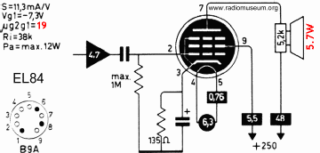
Thanks, Stan. I appreciate the explanation for the IC and NC. My lack of experience is showing and maybe I'm trying to simplify it too much. I pulled this image from the RMorg site on the EL84 and this is the type of datasheet that I have been referencing. Is there anything on this sheet that would show me that pin 1 and pin 2 are connected? If the information isn't on this sheet, what document would I look for to get that information? Again, I am simply connecting my multimeter leads to pins and checking for connectivity as a first step in determining if a tube has an obvious flaw.
I appreciate your guidance.
Mark
|
|
Stan Roberts
13.Apr.21 |
4
Mark, There is nothing on that sheet to indicate that Pins 1 and 2 are connected internally. That’s normal and that’s just how the convention has been interpreted over the years when it comes to internal connections. I don’t think you’ll find any additional information that discusses internal connections. I grew up at the very end of the vacuum tube era, so I yield to the experts here when it comes to the vagaries of tube design and pinouts. Perhaps unused pins were used to aid the mechanical and internal construction, support and rigidity as dimensional tolerances were very important in the control of electrical parameters. This arose because many of the B9A tubes were merely ‘shrunken’ versions of earlier octal and side contact types and so required improved physical and dimensional tolerances for improved efficiency and frequency response. In this respect, the EL84 seems to be an overgrown version of the older Rimlock EL41, which is itself a derivative of the earlier EL3. For years, we’ve tended to think of die-shrinking as a normal technique in the advancement of semiconductor design, but perhaps we overlook that vacuum tube technology went through similar iterations in design a couple of generations ago that eventually resulted in Nuvistors (6CW4/7586) and sub-miniature tubes such as the 1AD4/DF62. Enjoy the vicissitudes of an earlier technology! Stan Roberts |
|
Mark Pennington
13.Apr.21 |
5
Thank you, Stan, that is a big help and answers my primary question. I was driving myself crazy looking at datasheets to figure out pin connectivity for my basic tube test. On the EF86, you stated that pins 2 and 7 are connected by an internal screen. The tube that I have shows pins 2, 3 and 7 are connected. Does that make sense to you? I don't have another tube to compare it to.
Thanks, Mark |
|
Stan Roberts
13.Apr.21 |
6
Mark, That doesn't sound right to me that the cathode (Pin 3) is internally connected to the screen (Pins 2 and 7). I checked a couple of tubes that I have here, both are Mullard, one an EF86 and the other the higher grade version M8195. Pin 3 does not show a connection on either sample, so I can only conclude that yours has an internal short. It still may be usable as long as you let the screen float at the tube socket, but that may sacrifice some of its low noise/hum quality. Fortunately, you can still find these tubes at low cost on eBay. Kind regards, Stan |
|
Mark Pennington
13.Apr.21 |
7
Thanks, Stan. That's a huge help and I appreciate all your other information. All very helpful and much appreciated.
Mark |
|
Mark Pennington
30.Apr.21 |
8
Hello Stan:
I'm working my way through this and thought of your comment about the acoustically coupled tube base. I am not familar with those. Do you have any information on those or can you direct me to a source of information? Thanks,
Mark |
|
Stan Roberts
30.Apr.21 |
9
Hello again Mark. These tube bases are commonly known as anti-vibration or vibration-resistant bases and are still available on the web. I also found a different type, which was a thick rubber sleeve on a 6267 tube (a close equivalent to an EF86) in an old Akai M7 tape recorder. I assume it was intended to dampen out any motor vibration. Examples are shown below. You may also be able to fashion a homebrew version by using rubber grommets as shock mounts in the chassis in a similar way to how tuning capacitors were frequently chassis mounted in tube radios. Does that help? Kind regards.
Attachments
|
|
Mark Pennington
01.May.21 |
10
Yes, thanks, that does help. I'm in the process of troubleshooting this little amp and it's exhibiting problems that I haven't encountered before (I'm new to the hobby). I'm not sure the EF86 is the issue, but your suggestions may be part of the answer.
Thank you,
Mark |

|
Hits: 9235 Replies: 0
EL84 (EL84) mit "weichen Anschlußstiften"
|
|
|
Rüdiger Walz
13.Jul.08 |
1
In diesem Thread wurde nach einer EL 84 vom Funkwerk Erfurt mit weichen Anschlußstiften gefragt. Zufällig fand ich unter ECH 11 eine Variante wo eine ECH 81 mit weichen Anschlußstiften als Ersatzröhre verwendet wurde. Es ist zu vermuten, dass die beschriebene EL84 ebenfalls diesem Zweck diente. Rüdiger Walz |
|
Hits: 8961 Replies: 0
EL84 (EL84)
|
|
|
Vincent de Franco
24.Apr.07 |
1
Pentode de puissance |
|
Hits: 14482 Replies: 2
6P14P &EL84
|
|
|
Omer Suleimanagich
08.Jun.05 |
1
What is the differnece in these two vaccum tubes, and which one is supposed to be more powerful? Omer |
|
Hans M. Knoll
08.Jun.05 |
2
Hallo Mr. Omer Suleimanagich at the moment i am working in this area with different Tubetesters and Amplifiers. The end ist far. Here without comment, measurments from me. Please study this. The foreign samples are 6BQ5 Regards from Hans M. Knoll, Attachments
|
|
Omer Suleimanagich
13.Jun.05 |
3
Does this mean that the Telefunken is being used as the base measure? How does the Yugoslav EI variant EL84 ,based on Philips manufacturing techniques, or the JJ Tesla (Slovak) variant compare with all of this? Omer |
|
Hits: 16934 Replies: 12
EL84: Pin 8
|
|
|
Gottfried Silberhorn
08.Jan.05 |
1
ich hab noch eine Anmerkung zur EL84: der Stift 8 ist in Wirklichkeit KEINE innere Verbindung (iV), sondern einfach offen (englisch: nc, not connected) ! Ich kenne ein Radio, da wird dieser Pin als Verdrahtungs-Stützpunkt benutzt. MfG, Silberhorn |
|
Wolfgang Bauer
08.Jan.05 |
2
Sg. Herr Silberhorn. Sie haben natürlich recht, nach dem Telefunken Röhrenhandbuch 1969 sind die Pin's 1, 6 und 8 frei. Ich habe das Sockelbild zur Röhre neu hochgeladen. EL 84 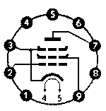 Mit den besten Sammlergrüßen Wolfgang Bauer |
|
Mario Tieke
08.Jan.05 |
3
Hallo Die mit "iV" bezeichneten Pins sind immer frei zu lassen und nicht als Lötstützpunkt zu verwenden. In den Datenblätter der Hersteller steht es meistens, das die als "iV" bezeichneten Pins nicht benutzt werden dürfen. Bei meinen EL84 ( Telefunken, Valvo, RFT, Funkwerk Erfurt, Polam), auch PL84, UL84 sowie die russischen Ersatztypen sind Pin 1 und 2 intern mit dem Steuergitter verbunden. Bei den russischen Ersatztypen sind die Pins 6 und 8 als Stütze für's System teilweise mit den Elektroden verbunden. Bei der PL82 von Telefunken sind die Pins 1,6 und 8 frei. Gruß Mario |
|
Gottfried Silberhorn
09.Jan.05 |
4
ja, Herr Tieke hat Recht, was ich gesagt habe gilt nur für die EL84 und dort nur für Pin 8. Der ist offiziell ein "iV", aber wie gesagt ich habe in einem Radio gesehen, daß an Pin 8 ein Kondensator und ein Draht angelötet war. Diese "Beschaltung" hat mich zuerst ziemlich verwirrt, dann habe ich mal einige EL84 genau angeschaut, und gesehen, daß Pin 8 immer innerlich offen ist. MfG, G. Silberhorn |
|
Peter von Bechen † 15.7.19
09.Jan.05 |
5
Hallo, in der Röhren-Taschen-Tabelle (RTT) von Schwandt findet man den Hinweis: "An die mit iV bezeichnten Stifte darf keine Schaltverbindung angeschlossen werden, da dann Kurzschlüsse entstehen können!" In der RTT ist bei der Sockelschaltung der EL84 (No 20) bei Pin 8 "iV" angegeben. Auch im Röhrenhandbuch von Ratheiser (Siehe unten nur mit "i"). Die Röhrenhersteller haben damals davor gewarnt, die iV-Pinner insbesondere bei Allglastypen anderweitig zu beschalten, weil diese im Innern als Stützpunkt für das System gebraucht werden. Auch wenn es bei vielen Röhren, die auf den Markt kamen, nicht bei allen iV-Stiften der Fall war, wie hier beim Pin 8 der EL84 - es gab keine Garantie, dass sich das irgendwann durch konstruktive Änderungen ergeben konnte. Deshalb sind iV-Anschlüsse tunlichst nicht als Lötstützpunkte zu benutzen. Dass es in manchen Radios trotzdem geschah, liegt sicherlich daran, dass die Konstrukteure mit den Lötpunkten sparsam umgehen mussten und zusätzliche Lötleisten einfach eingespart haben. Aber wie gesagt: Es gab und gibt keine Garantie, dass alle auf dem Markt erhältlichen EL84 unterschiedlicher Produktionschargen und verschiedener Hersteller in diesen Geräten funtionieren.  |
|
Gottfried Silberhorn
10.Jan.05 |
6
ich schlage vor, den EL84 Text folgendermaßen zu ergänzen: "Wenn in einem Radio an Pin 8 etwas angeschlossen ist, dann ist das nur ein Lötstützpunkt. In der Röhre ist Pin 8 offen" Einverstanden ? G. Silberhorn |
|
Mario Tieke
11.Jan.05 |
7
Hallo Der Hinweis wäre besser beim entsprechenden Gerät aufgehoben und nicht bei der Röhre. Ich habe durch Zufall eine EL84 in meiner Sammlung gefunden, bei der die Anode mit Pin 7 und 8 verbunden ist. Bei der UL84 und der PL84 ist es ähnlich. Gruß Mario 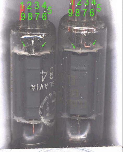
|
|
Jacob Roschy
11.Jan.05 |
8
Hallo Herr Silberhorn, damit bin ich genau nicht einverstanden, denn die wichtigste Angabe fehlt. Man könnte diese Problematik vielleicht so beschreiben: "Die Stifte 1; 6 und 8 der EL84 (wie auch andere Röhren, die diese Sockelschaltung haben,) werden nicht als Elektrodenanschlüsse benötigt. Je nach Fabrikat sind sie völlig frei oder werden in der Röhre als Stützpunkte verwendet. Manche Gerätehersteller verwendeten jedoch die entsprechenden Lötösen der Fassung ebenfalls als Stützpunkte. Bei einem Röhrentausch muss darauf geachtet werden, dass die neue Röhre keine interne Verbindung hat, wo ein solcher Lötstützpunkt vorhanden ist." MfG JR |
|
J. H.
12.Jan.05 |
9
Hallo, das Fazit aus diesem Thread sollte sein: bei jedem Röhrentausch zunächst die Beschaltung des Röhrensockels auf Belegung von im Röhrendatenblatt als "n.c" /"i.c"/"i.v" bezeichneten Stiften überprüfen. Es ist einfach erschreckend, dass sich Hertseller zu solch gefährlichem Unsin haben hinreißen lassen. An die Kostengründe kann ich da kaum glauben. Ich denke eher, dass es schon damals darum ging, dass nur Ersatzteile vom Hersteller verwendet werden sollten. Dass man dabei aber in Kauf nahm, dass bei einem Röhrentausch evtl. ein anderes Bauteil zerstört wird oder auch nur einfach die Funktion unmöglich gemacht wurde, wirft ein sehr schlechtes Licht auf solche Hersteller. Bei z.B. Sony hat man in späteren Jahren einen anderen "Trick" verwendet: es wurden Bauteile verwendet, die auf dem freien Markt einfach nicht erhältlich waren und noch nicht einmal in Vergleichlisten auftauchten. Dadurch war man auf Gedeih und Verderb dem Hertsteller und dessen Preisgestaltung ausgeliefert. Ich habe nie ein Sony-Gerät gekauft, aber oft genug repariert - da konnte dann ein simpler Thyristor schon mal 25 DMchen kosten, wenn man ihn überhaupt bekam ... Gruß Jürgen Heisig |
|
Peter von Bechen † 15.7.19
13.Jan.05 |
10
Hallo, hier ist der Ausschnitt eines Bildes der EL84 aus einer Valvo-Publikation der 60er Jahre. Hier sieht man, dass Pin 8 als Stütze für den rechten Steg von G3 benutzt wird. Gruß Peter von Bechen 
|
|
Wolfgang Bauer
13.Jan.05 |
11
Hallo, die Hersteller haben sich normalerweise etwas gedacht, wenn sie die Nachbarpunkte des Anodenanschlusses freigehalten haben, um Überschläge zu vermeiden. Zusätzlich treten bei offenem Lautsprecheranschluß an der Anode extrem hohe Spannungsspitzen auf, die bei belegten Nachbarkontakten durch Lichtbogenbildung weitere Schäden im Gerät verursachen können. Besonders Pertinaxsockel sind so ganz schnell verschmort. Siehe auch den Beitrag von Herrn Knoll im Treat: http://www.radiomuseum.org/dsp_forum_post.cfm?thread_id=39493 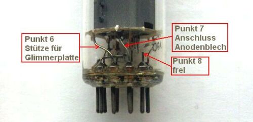 Besten Gruß Wolfgang Bauer |
|
Jacob Roschy
13.Jan.05 |
12
Es wäre unmöglich und auch nicht zweckmäßig, bei all den vielen Röhren, die interne Verbindungen an nicht benötigten Stiften haben, einen Warnhinweis über eventuelle Lötstützpunkte in Geräten anzubringen. Vielmehr sollte dieser Hinweis besser bei entsprechenden Geräten angebracht werden, die in dieser Hinsicht auffällig wurden, wie schon zuvor erwähnt. Der Fehler liegt am Gerät, nicht an der Röhre, abgesehen davon, dass er sich dort auch nicht ändern lässt. Es kann praktisch ausgeschlossen werden, dass Gerätehersteller bestimmte Lötfahnen von Röhrenfassungen als Verdrahtungsstützpunkte wählten, nur um Bau- und Ersatzteile inkompatibel zu machen. Hierzu hätte jeder Gerätehersteller seine eigene Röhrenproduktion haben oder sich Röhren maßanfertigen lassen müssen, was jeweils als absurd erscheint. Dies waren nur Kostengründe kombiniert mit Leichtsinn. MfG JR |
|
Wolfgang Bauer
19.Jan.05 |
13
Anbei noch ein Datenblatt von Telefunken, bereitgestellt von Herrn Knoll. Ich habe den Text unter der Röhre nochmals herausgeschrieben, weil er sonst kaum lesbar ist. Freie Stifte bzw. freie Fassungskontakte dürfen nicht als Stützpunkte für Schalt- mittel benutzt werden. 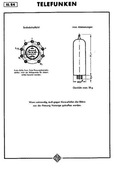 MfG. Wolfgang Bauer |
End of forum contributions about this tube
| Data Compliance | More Information |