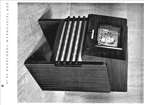
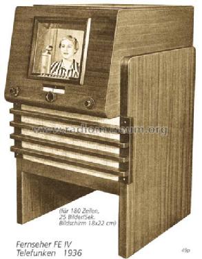
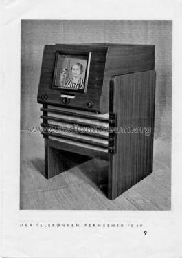
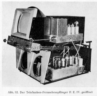
Fernseh-Empfänger FE IV (4)
Telefunken Deutschland (TFK), (Gesellschaft für drahtlose Telegraphie Telefunken mbH
- Country
- Germany
- Manufacturer / Brand
- Telefunken Deutschland (TFK), (Gesellschaft für drahtlose Telegraphie Telefunken mbH
- Year
- 1935–1937
- Category
- Television Receiver (TV) or Monitor
- Radiomuseum.org ID
- 4341


D_Telefunken_FEIV_Werbefoto

Funk 1936, Heft 6, S 187-90
Funk 1936, Heft 6, S. 187-90

Funk 1936, Heft 6, S 187-90

Funk 1936, Heft 6, S 187-90
Funk 1936, Heft 6, S 187-90

Funk 1936, Heft 6, S 187-90

Funk 1936, Heft 6, S 187-90


Click on the schematic thumbnail to request the schematic as a free document.
- Number of Tubes
- 17
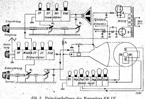
- Main principle
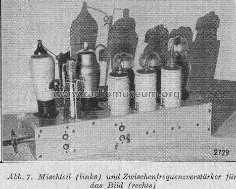
- Superheterodyne (common); ZF/IF 1300/3100 kHz
- Wave bands
- Wave Bands given in the notes.
- Power type and voltage
- Alternating Current supply (AC) / 110; 220 Volt
- Loudspeaker
- Permanent or electro-dynamic (moving coil), system not known yet.
- Material
- Wooden case
- from Radiomuseum.org
- Model: Fernseh-Empfänger FE IV - Telefunken Deutschland TFK,
- Shape
- Console with any shape - in general
- Dimensions (WHD)
- 580 x 999 x 840 mm / 22.8 x 39.3 x 33.1 inch
- Notes
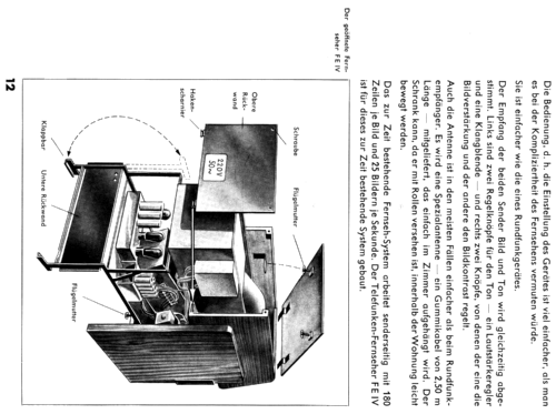
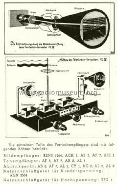
- UKW 40 - 55 MHz. 180 Zeilen. 25 Bildwechsel / s.
Parallelton-Empfänger. Bildgröße 18 x 22 cm.
Röhrenanzahl laut Holtschmidt: 18. Im Prohaska-Katalog 1935/36 (und dem Katalogblatt des deutschen Rundfunkmuseums) wird eine AB3 als Ton-Demodulatorröhre angegeben, was ein Druckfehler gewesen sein dürfte.
- Source of data
- Katalog Radio-Zentrale Alex v. Prohaska 1935/1936 / Radiokatalog Band 1, Ernst Erb
- Mentioned in
- D.Holtschmidt: Fernsehen wie es begann.
- Picture reference
- Das Modell ist im «Radiokatalog» (Erb) abgebildet.
- Other Models
-
Here you find 3581 models, 3168 with images and 2126 with schematics for wireless sets etc. In French: TSF for Télégraphie sans fil.
All listed radios etc. from Telefunken Deutschland (TFK), (Gesellschaft für drahtlose Telegraphie Telefunken mbH
Literature
The model Fernseh-Empfänger is documented in the following literature.
Forum contributions about this model: Telefunken: Fernseh-Empfänger FE IV
Threads: 1 | Posts: 1
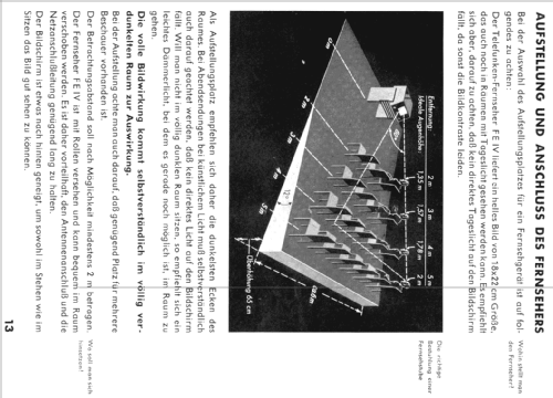
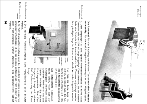
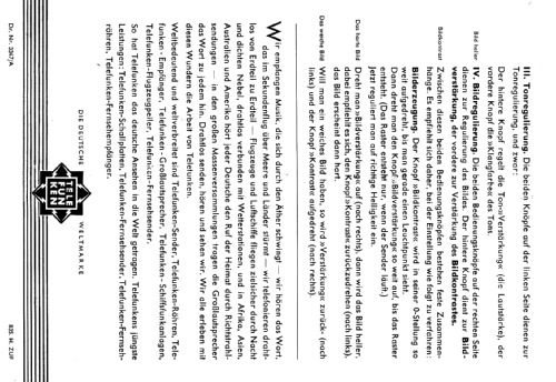
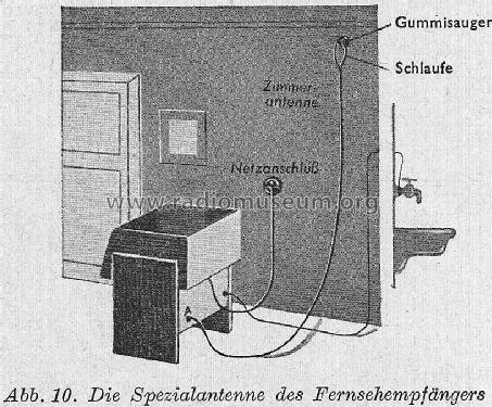
Ein Telefunken-Prospekt von1935 zeigt auf 16 Seiten in vielen Bildern und Trickzeichnungen dem interessierten Laien wie Fernsehen funktioniert , wie der Fernseher aufgebaut ist und wie einfach man ihn bedienen kann.
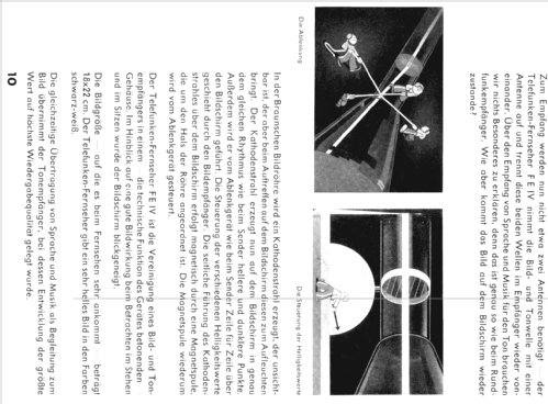
Auf dem Funkturm Berlin-Witzleben sind die beiden UKW-Antennen für Bild und Ton gezeigt.
Auf dem Funkturm Berlin-Witzleben sind die beiden UKW-Antennen für Bild und Ton gezeigt.
Tilo Heyl, 27.Dec.06