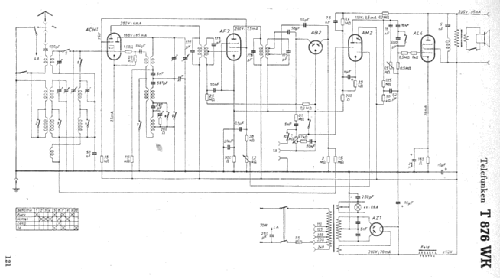
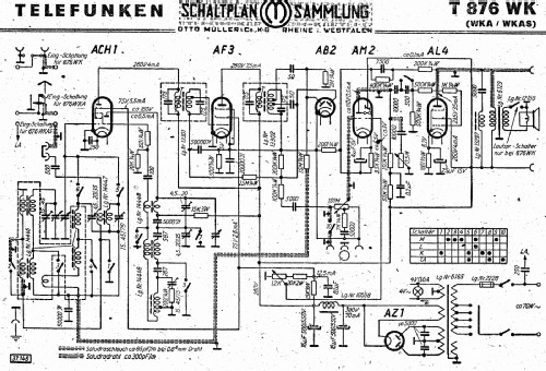
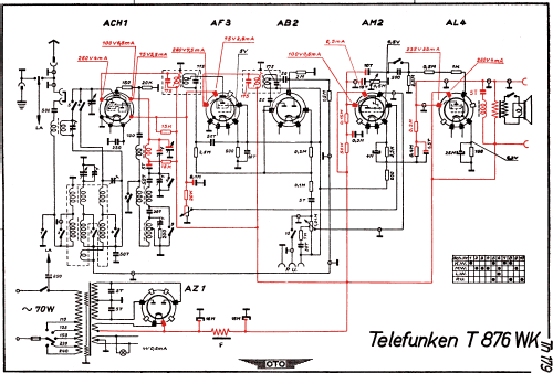
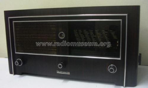
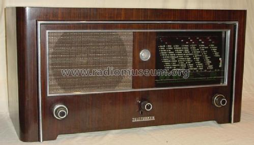
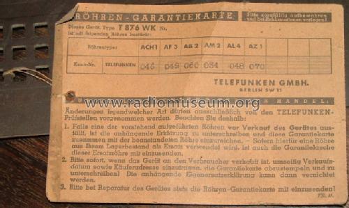
Gross-Super 876WK (T876WK)
Telefunken Deutschland (TFK), (Gesellschaft für drahtlose Telegraphie Telefunken mbH
- Country
- Germany
- Manufacturer / Brand
- Telefunken Deutschland (TFK), (Gesellschaft für drahtlose Telegraphie Telefunken mbH
- Year
- 1938/1939
- Category
- Broadcast Receiver - or past WW2 Tuner
- Radiomuseum.org ID
- 4283
Kaunas Lithuania
Kaunas Lithuania
ebay
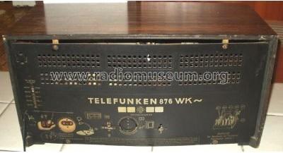
Telefunken Type 876WK
ebay
Kaunas Lithuania
Kaunas Lithuania
Kaunas Lithuania
Kaunas Lithuania
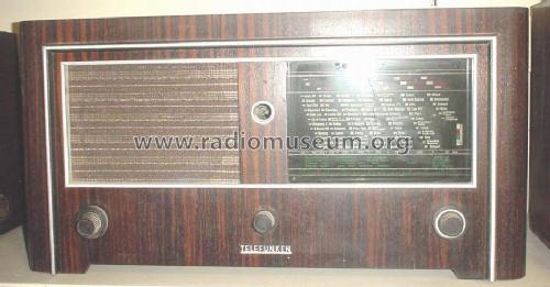
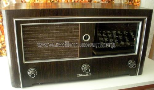
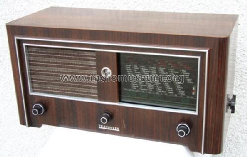
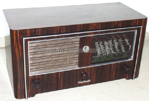
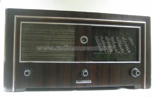
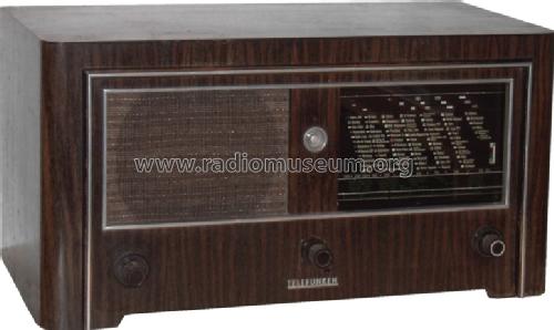
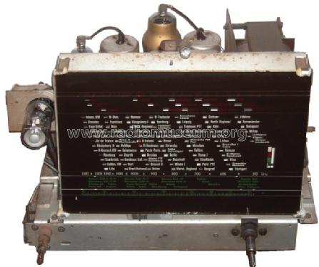
Frontseite
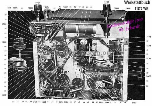
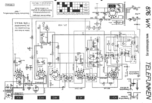
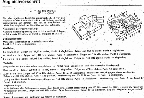
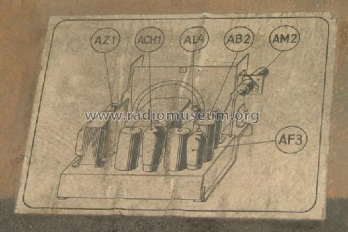
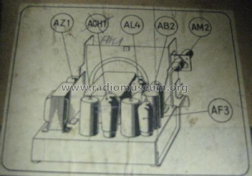
Aus Telefunken Werkstattbuch 1938/39
Click on the schematic thumbnail to request the schematic as a free document.
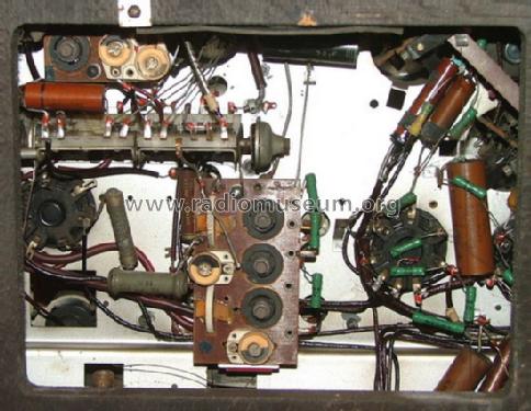
- Number of Tubes
- 6
- Main principle
- Superheterodyne (common); ZF/IF 468 kHz
- Tuned circuits
- 7 AM circuit(s)
- Wave bands
- Broadcast, Long Wave and Short Wave.
- Power type and voltage
- Alternating Current supply (AC) / 110-240 Volt
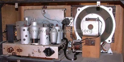
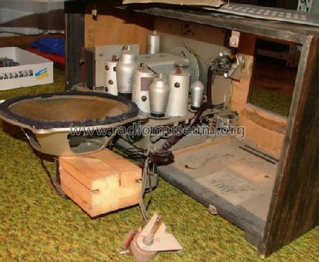
- Loudspeaker
- Electro Magnetic Dynamic LS (moving-coil with field excitation coil)
- Material
- Wooden case
- from Radiomuseum.org
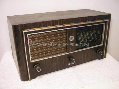
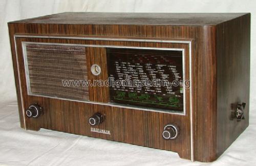
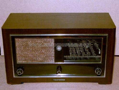
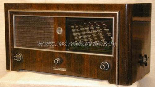
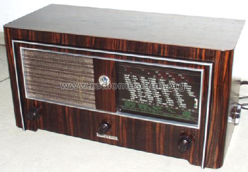
- Model: Gross-Super 876WK - Telefunken Deutschland TFK,
- Shape
- Tablemodel, low profile (big size).
- Dimensions (WHD)
- 670 x 334 x 331 mm / 26.4 x 13.1 x 13 inch
- Notes
-
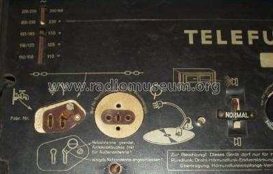
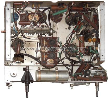
Bandfiltereingang für LW und MW.
Variable Bandbreite.
- Net weight (2.2 lb = 1 kg)
- 16.6 kg / 36 lb 9 oz (36.564 lb)
- Price in first year of sale
- 298.00 RM
- Source of data
- Handbuch WDRG 1938 / Radiokatalog Band 1, Ernst Erb
- Circuit diagram reference
- Lange+Schenk+FS-Röhrenbestückung
- Picture reference
- Eine Abbildung findet sich im Doppelband "Radios von gestern"
- Other Models
-
Here you find 3550 models, 3130 with images and 2095 with schematics for wireless sets etc. In French: TSF for Télégraphie sans fil.
All listed radios etc. from Telefunken Deutschland (TFK), (Gesellschaft für drahtlose Telegraphie Telefunken mbH
Collections
The model Gross-Super is part of the collections of the following members.
- Peter Breu (D)
- Hartmut Daniels † 22.11.16 (D)
- Peter Degenkolbe (D)
- Hans-Werner Ellerbrock (D)
- Karlheinz Gützlaff (D)
- Gerhard Held (A)
- Reinhard Hopfe (D)
- Juha Lahtinen Liljeroos (FIN)
- Zenonas Langaitis (LT)
- Dieter Michel (D)
- Nico Pokrant (D)
- Marian Popov (BG)
- Timo Rantasaari (FIN)
- Manfred Rathgeb (D)
- Andreas Reuther (D)
- Reinhard Riek (D)
- Dieter Schulte-Kulkmann (D)
- Alois Steiner (A)
- Martin Steyer (D)
- Urmas Tingas (EST)
- Werner Veitweber (D)
Forum contributions about this model: Telefunken: Gross-Super 876WK
Threads: 3 | Posts: 8
Liebe Sammlerkollegen,
zur Aufarbeitung meines Telefunken 876 WK suche ich die rechte Zierleiste, oder ein Gehäuse wo sie noch vorhanden ist. Über Angebote würde ich mich freuen.
Mit freundlichem Gruß,
Nikolaus
Löwe
Nikolaus Löwe, 27.Oct.11
Gentlemen,
Like Mr Carabas,
I am also beginning the alignment procedures on the early 1937/1938 Telefunken receivers; however, I am somewhat still curious to explain some minor circuit changes (or improvements).
In my model T776WK, the mixer-oscillator tube ACH1 does not reflect the addition of the small 250pF capacitor which bridges the kathode and the filament pins???
Then in the output stage, from the audio pre-amp in the AM2 tuning eye to the control grid, there is the identical coupling capacitor and the 0.5M ohm resistor phowever, the 776WK places a final 100 ohm resistor entering the grid. . . . . . .while in the 876WK the circuitry the corresponding resistor is rated for 1K ohms.
Are these 2 small parts significant enough to render the receiver "muted" if not precisely followed?
One last question - although I have had the radio for some time, I was not able to locate dropping resistor R43. If the previous owner (or technician) removed the item and did not replace it; could the item have been mounts somewhere on the loudspeaker assembly??
Respectfully,
Robert
I would also like to express my sincere Appreciation and Thanks to member Mr Hugo Sneyers for the replacement of the complete BF2 cylinder - without which the Telefunken Gross-Super could not be "restored". . . . . . . . . .
NOTE: I have prepared what I believe to be a complete "TFK 776WK Alignments" procedural checklist (in English) if one of the radio engineers would be kind enough to review my efforts. I have not yet "folded in" the Illustrations, but I have included a brief description of the needed graphics. I have also included the use of my recently acquired Rohde & Schwarz BN4114 Signal Generator as one of the principal test equipment items.
Robert Sarbell † 22.3.22, 31.Jul.11
Dear collegues,
I need your help. From a long time I am trying to restaure an Telefunken 876 wk.
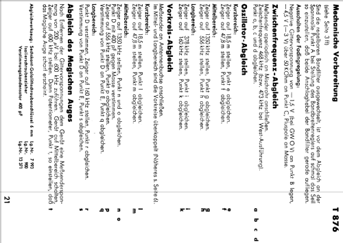
I am now at the alignment stage of both medium frequency trasformers. , or the 468 Kth frequency.
From speciality literature the aligment is done by opening the potentionmeter at hight sounds , obtaining in this way an width passing band.
At 876 wk radio device the primary medium frequency transformer is mobile and it can be rotated , being actioned by the knob wich adjust the tone.
The armature wich covers the medium frequency transformers have two holes to access the coils. The holes are positioned at 90 degrees one from another.
In this case, the access at the iron center of the coils is made when these are at 90 degrees one from another, wich correspond to low sounds on tone knob, where the passing band is contracting.
How can I proceed to align correctly the both medium frequency transformers?
This operation must be done because the condensers mountel in paralel with the coils have been changed because the original ones did not match.
Thank you,
Best regards,
Eng. Ion Carabas
Ion Carabas, 21.Mar.11