agabaltic: AGA-Baltic 2041 - dial string diagram
? agabaltic: AGA-Baltic 2041 - dial string diagram

My recently acquired AGA 2041 looks - after thorough cleaning - quite respectable. It even plays! The biggest problem noticed so far is a broken dial string. Has anybody the diagram (Schnurlaufbild) and would be so kind to upload it?

If that information proves unavailable, I shall be guided by the advice from Thomas Albrecht in a similar situation (December 2008). The Norwegian link recently posted by Wolfram Zylka did unfortunately not lead to the desired info.
Also, the tuning shaft sits rather wobbly in its sleeve. Judging by the fragments of black plastic falling from the assembly, the shaft may have been resting in two plastic rings - one on either side. As it is unlikely that original replacement rings can be located, I may have to "invent" something. I would appreciate to hear from anyone who experienced the same problem. Thanks.

To thank the Author because you find the post helpful or well done.
AGA 2041/1654 tuning cords
Hi Alfred.
It looks like that wiring of the tuning cords of your AGA 2041 seems to be very similar to my AGA 1654. The arrangement consists of three different cords; the thickest one turning the big wheel and turned around your wobbling knob shaft. Then one thin metal cord from the big wheel to the upper two-wheel arrangement wich is moving the scale indicator.
Going to make a drawing of the cords, but at first I have to take out the chassis from the cabinet and inspect thoroughly how theyare going.
It may take a couple of days before I'm ready with the drawing.
.
Regards
Lars-G.
- AGA_Cords1 (138 KB)
- AGA-cord2 (158 KB)
To thank the Author because you find the post helpful or well done.
AGA 2041/1654 tuning cords
It's simple! Only have a look at the three attached pics and you'll manage the assembling.
regards
Lars-G.
Attachments:- AGA_1654_Cords_knob Shaft (99 KB)
- AGA_1654_Pointer_cord (53 KB)
- AGA_1654_Steel_cord1 (83 KB)
To thank the Author because you find the post helpful or well done.
AGA-Baltic 2041 dial string
Hello Lars,
my sincere thanks for the quick reply and the action taken. I had anticipated that someone has the manufacturer's service documentation and would simply scan the respective page. I would have never asked you to disassemble your 1654 for this purpose. Now that it's done it is of immediate help to me and, I am sure, will in the long run benefit others as well.
The dial string arrangement on your 1654 is indeed very similar, if not identical, to the one on my 2041. I am fortunate that only the part that winds around the wobbly shaft is defective. The spring and a piece of frayed string are all that's left there. The rest is intact. With the aid of your sketch the problem should soon be taken care of.
Perhaps you can enlighten me on another point: I cannot find a fuse on my set. The power cord is definitely not original. By its looks it is of much later date and must have come from a heavy-duty household appliance. (14 gauge wire, the three-pronged plug bears the Westinghouse logo). Am I correct in assuming that original power cord came with a built-in fuse?
Regards, Alfred
To thank the Author because you find the post helpful or well done.
AGA-Baltic fuse
Hi Alfred!
It is generally difficult to get instruction manuals for any AGA and AGA-Baltic radios. Since my AGA-Baltic 1654 is an AC/DC set I think the similarities between our radios ends with the dial string assembly. In my set the main fuse is a visible common 400 mA glass tube fuse and as far as i know AGA did never install the fuse in the power cord.
You should look for the fuse very close to, or built-in, the mains transformer. It's probably a spring arrangement with soldering connection or a current limiting wire.
Regards and have good Valentine's Day
Lars-G.
To thank the Author because you find the post helpful or well done.
AGA 2041 fuse
Hello Lars,
You are dead on with your suggestion to look close to or at the mains transformer for a possibly built-in fuse. In the meantime I had the great fortune to receive an e-mail from the ultimate authority on this and most other subjects.
Hans Knoll writes: I noticed the concern about the radio possibly not having a fuse.
In Scandinavia fine wire fuses of the common type are not and were not integrated into the power cord. This is based on the assumption by the regulatory authorities that the customer may not change the fuse to another rating when an adjustment in the voltage setting would necessitate it. The same applies to Philips.
Instead, there is a thermal fuse at the transformer where the power comes in. It opens when the transformer gets too warm. At your radio it is here. (Attachment).
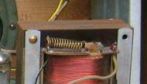

For over 30 years I looked after, respectively developed Scandinavian models at Grundig. Hans Knoll.
That certainly clarifies it for me.
To you and Hans my sincere thanks for all the help and advice.
Regards and "Happy Valentine" to you too
Alfred
To thank the Author because you find the post helpful or well done.
Dial cord schematic...

Hello there, Alfred!
I just stumbled over this forum, and I actually happen to have a lot of the original AGA-Radio service manuals (1943-1955) for a lot of AGA radio models, among other, I have the service manual for your 2041! (It's from the AGA-Radio RadioService Booklet of 1950/51)
So I have attached the Dial Cord Instruction for you here.
I have scanned it, and then I did some work to decrease the colors to only Black and White.. I think it has good quality. It's in PDF format.
I hope you find it useful!
Kind regards
/Jörgen Svensson
Attachments:
- AGA2041-42 DialCord diagram (190 KB)
To thank the Author because you find the post helpful or well done.
Dial Cord Diagram
Hello Joergen,
I almost overlooked your posting as my specific problem has already been solved through all the trouble to which Lars-G. Lundelin went in order to assist. But what you did is terrific. This will be a very valuable addition to the model page. Thanks!
Best regards,
Alfred
P.S: May RMorg look forward to more uploaded information from your obviously rich AGA library;-)?
To thank the Author because you find the post helpful or well done.
AGA documentation...
Well... I will certainly try to upload... The problem is that those old documents are more brownish-gray, so it is quite a time consuming work to get it in the clean white state that this dial cord diagram is... but I will certainly try to make an effort with this...
I intend to convert all my schematics into digital format, so I can have them on a computer in my workshop, easily accessible..
During this work, there will certainly be some uploads done to RMorg...
Take care!
/Jörgen
To thank the Author because you find the post helpful or well done.
Scans with oversampling

Dear Jörgen,
for scanning schematics I use an oversampling method which gives good results and is easy to apply. Text in German see here:
The way is the following:
- scan in black/white with 600dpi; this will give a size of 3000 points or even more
- adjust gradation in order to get a good b/w scan, grey will become white; better a bit too light than too dark
- the scan might now look a bit fraied, however, after the next step it will become good
- change the size of the figure to 2200 points width and a resolution of 300dpi: this is downsampling
- change the colour to 4 steps (black - grey - white)
- edit white to 255 and black to 0
- save the file as a .png
I use Irfanview and get a prettiy schematic with a few clicks only
I hope, this will help you to save work when you are scanning schematics.
Best regards,
Dietmar
To thank the Author because you find the post helpful or well done.