C-Quam AM Stereo Transmitter Using Valves
C-Quam AM Stereo Transmitter Using Valves
Over the last couple of years, I've experimented with a number of low power transmitters for broadcasting music to the antique radios in my house. For some time I've been thinking of the possibility of building a low power C-Quam Stereo AM transmitter. Although I don't have any AM stereo receivers that would meet the definition of antique, it remains an intriquing challenge. My goal is to do it with vacuum tubes, preferably a modest number of no more than two or three (excluding power supply). I decided to approach the project with healthy dose of naïvete; otherwise I'd likely never attempt it. However, fools rush in where wise men fear to tread.
To start, I decided to review the manner in which C-Quam works.
Figure 1 is a block diagram of the C-Quam AM stereo system that was developed and promoted by Motorola, and which eventually became the standard used in North America, and I believe most of the rest of the world.
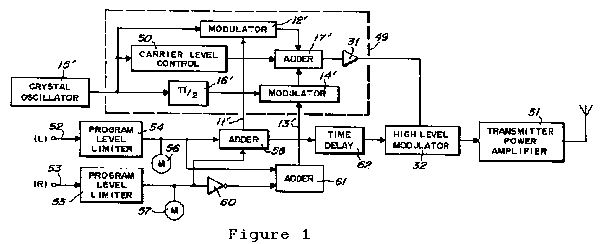
The receiving system is not included in the diagram, and won't be covered in this discussion. German readers may refer to the excellent article on AM stereo by Prof. Dietmar Rudolph. Please refer also to the Motorola C-Quam patent [1]. (See bottom of this page for numbered references.)
In the C-Quam system, the Left and Right audio signals are combined into L+R and L-R signals, and then are used as the modulating signals in a quadrature AM modulator. The output of the quadrature modulator is an AM signal with an envelope similar to (but not exactly the same as) a standard AM signal. There are enough differences in the envelope, that if it is received on a standard monaural AM radio with an envelope detector, there will be offensive distortion components. To avoid this, the C-Quam system, adjusts the envelope of the signal from the quadrature modulator so that it is essentially the same as that of a regular envelope modulator. It turns out that the easiest way to do this is to pass the quadrature AM signal through a limiter leaving a constant amplitude phase modulated signal which is subsequently modulated by a standard envelope modulator.
This begs the question: What would happen if the quadrature modulator and limiter were to be replaced by a simple phase modulator? Would anyone notice the difference?
If the quadrature modulator is a completely general type, accepting a pair of completely arbitrary inputs, then the resulting phase could vary over a range of 180° and would be a complex function of both the I and Q baseband signals. And by "complex" I imply both meanings: mathematical, and that which confuses humans. Undoubtedly a simple phase modulator would not be an adequate replacement in that case. However, the real world audio signals are subject to a few constraints which restrict the range over which the phase may vary. It's instructive therefore to look at the actual signals which are applied to the quadrature modulator in a C-Quam system.
Figure 2 is a vector diagram showing the relationship of the signals in a quadrature modulator. In this system, there are two carriers with a relative phase difference of 90°. The L+R signal modulates In-phase carrier (horizontal axis), and the L-R signal modulates the Quadrature carrier (vertical axis). Also, the L+R signal is given a DC bias so that the modulated signal is always positive. In the figure, the green vectors represent an L+R signal with an instantaneous value of 0.5. The heavier line indicates the minimum excursion of the carrier, and the thinner line represents the maximum excursion of the carrier. The L-R signal has no DC offset, and so any modulation of the Q carrier will produce equal excursions above and below the I axis. The red vectors represent an L-R signal with an instantaneous value of 0.5. As can be seen, the carrier excursions go from +0.5 to -0.5. In order to fall within allowable modulation limits, the L+R and L-R signals are limited to the range of ±1 (arbitrary units). By extension, the L and R signals are therefore limited to the range of ±0.5. (I have inferred these limits not from having discovered any hard evidence on C-Quam specifications, but since Figure 1 shows no cross limiting between Left and Right channels, I believe my assumption is valid.)
For this discussion, I will be using the following convention for the quadrature modulation of the audio signals:
I=(1+L+R)sin(ωt)
Q=(L-R)cos(ωt)

The definition of quadrature modulation is sufficiently general that the sine and cosine functions could be swapped between the I and Q functions, and a negative sign could appear in either or both terms. In any case, the signals can still be completely recovered by a suitable pair of synchronous demodulators operating 90 degrees out of phase. The only significant difference that may be encountered is that depending on the convention chosen, the vectors may rotate in opposite directions to those of a different convention. The final effect will be that one of the signals, as ultimately demodulated, may need to be inverted. I mention this, because I used the Motorola patent as my primary source of information, and while I searched for other documents giving more specific details of the implementation of the actual commercial system, I wasn't able to nail down the exact polarities, and have therefore chosen my own convention for this discussion. I welcome any and all corrections.
Figures 3a through 3f are vector diagrams showing the resultant carrier for various inputs, after the I and Q signals have been combined. In the simplest case of a monaural signal (Fig. 3a), the L-R signal is zero, and the L+R signal is equal to the monaural audio. The carrier is a vector whose tail is at the origin, and the tip follows the audio signal, remaining on I axis at all times.


Next (Fig. 3b), consider an audio signal which appears in the left channel only. Assume an amplitude of 0.5, the maximum allowable value. The right signal is zero, and hence L+R=0.5 and L-R=0.5. Because the carriers are in quadrature, the tip of the carrier vector traces a circle rather than a straight line. The black circle is the actual locus traveled by the tip of the carrier vector. Now consider a signal which appears only in the right channel and again with an amplitude of 0.5. We calculate L+R=0.5 and L-R=-0.5. Interestingly, the carrier traces exactly the same locus. The difference is in the direction of rotation. For the Left-only signal, the rotation is clockwise, and for the right-only signal, the rotation is counter-clockwise.


As an audio signal pans from the left channel, though centre and then to the right channel, the circular locus becomes flatter until (at the exact point it passes through midpoint of the soundstage) it is a horizontal line on the I axis, and then starts to inflate into a circle again (with the direction of rotation now reversed) as it moves on to the right side (Fig. 3c). It is also possible for the locus to trace a vertical line (Fig. 3d) or a nearly vertical ellipse in the case of two similar L and R signals which are nearly 180° out of phase. In this case, because of the input signal limiting, the maximum phase angle is ±26.57°. However, regardless of the combination of the possible signals which may be present, the phase angle ø will never deviate by more than ±30 degrees. This occurs in a signal of maximum amplitude which occurs in a single channel only (Fig. 3e).
.PNG)

Figure 3f shows a signal which would meet the requirements of the quadrature modulator in that the magnitudes of both the L+R and L-R signals are equal to one. However, this can only be achieved by setting L=1 and R=0 which according to the earlier specification cannot exceed a value of 0.5. Nevertheless, it is interesting because it shows that if it were allowable, the magnitude of the vectors must rapidly decrease as the phase angle increases beyond 45°. Hence if this type of signal were allowed, the amount of energy in large phase deviations is very small. When I initially decided to pursue this line of investigation, I hadn't ruled out the possibility of this situation, but on the basis of the limited energy in the extremes excursions, it seemed to me that the distortion due to a simplified phase modulator may still fall within acceptable limits. Ultimately, it appears that such an extreme condition cannot occur.
At this point we have covered Quadrature modulation, or Quam. In order to make it compatible with existing monaural AM receivers, the envelope must be distorted slightly in order to match the envelope of an equivalent monaural signal composed of the L+R modulation. It turns out that the most practical way to do this is to pass the quadrature signal through a limiter, thus stripping off all existing amplitude variations, leaving only the phase modulation. Then it is re-modulated using a conventional amplitude modulator.
The effect of limiting is illustrated in Figure 4. The red unit semi-circle represents the resulting amplitude of the limited signal. the vector loci of the previously discussed signals are projected onto this semi-circle as a result of the limiting. Three example vectors are shown. Vectors 1 and 3 extend from their original positions on the locus (black dots) to the unit semicircle, and vector 2 retracts from its original position to the semicircle. Hence we now have a constant amplitude phase modulated signal. Although the output of the quadrature modulator is a function of both the L+R signal and the L-R signal, it is readily apparent that because of the ±30° limits, the locus is a mainly vertical arc which is primarily a function of the vertical L-R signal, and secondarily a function of the L+R signal. If the limitations on the input signal amplitudes were relaxed, it would be possible for the locus to deviate ±90° or more, and in the region from +45° to +90° and the region from -45° to -90°, where the arc becomes horizontal, it is primarily a function of the L+R signal and secondarily a function of L-R. At exactly +45° and -45° the L+R and L-R signals contribute equally to the phase angle.

It seems plausible then, that the quadrature modulator and limiter could be replaced with a simple phase modulator circuit which is modulated only by the L-R signal. Obviously, it will not reproduce the required signal perfectly, thus introduction some distortion. It is apparent that the worst distortion will occur when the output phase is at or near the ±30° limits. However, this is a situation which corresponds to a signal appearing only on the left channel or only on the right channel. Statistically, this occurs infrequently, and therefore may go unnoticed. The human ear is often very forgiving of certain types of distortion, particularly when buried in among other sounds. Psychoaccoustics can mask a lot of sins. Consequently, it seems worth proceeding with the design of a simplified phase modulator circuit. This will be discussed in Part II.
Meanwhile, comments, questions and suggestions are always welcome.
References
1. Parker, N. W., Hilbert, F. H.; Compatible AM Stereo Broadcast System; US Patent 4,218,586.
To thank the Author because you find the post helpful or well done.
Part II - The Phase Modulator
A rather appealing Phase Modulator circuit is this simple reactance tube implementation shown in Figure 5 (see Terman [2] page 604). The details of powering the circuit and biasing have been omitted in this simplified drawing.
.PNG)
This circuit is configured in such a way that the phase shift between the input signal E1 and output signal E3 is a function of the vacuum tube's transconductance g, but the amplitude of the signal remains constant. However, the input and output impedance of this circuit do change, and this requires that the input either be a very low impedance voltage source, or a very high impedance current source in order to prevent interaction between circuits. Additionally, the load placed on this circuit must be a high impedance. The phase shift is a function of transconductance which in turn is a function of grid bias. Terman gives only a brief discussion of the circuit, but attributes the design to Beleskas [3] from which an in-depth analysis can be found. Suffice to say, the phase shift function is given by:
ø=2arctan|Xg|
where:
Ø is the phase shift,
X is the reactance indicated in the circuit diagram
g is the vacuum tube transconductance.
The reactances may be either capacitive or inductive.
This reactance function is charted in Figure 6:

Stating the obvious, the function is rather non-linear. In our search for a linear phase modulator it doesn't look too promising. But we're not done yet.
Figure 7 shows the transconductance characteristics of the tetrode section of a 6CQ8 triode/tetrode taken from the General Electric Vacuum Tube Guide.

It can be seen that these curves bend in the opposite direction to the curve of Figure 6. So, by choosing the appropriate screen voltage and grid bias, it may be possible to linearize the phase shift function over some useable range. The data from the transconductance curves were entered into a spreadsheet table, and then applied to the phase shift function. Using 100pF capacitors for the reactors, and an operating frequency of 1500kHz (giving a reactance X of 1061 ohms), and a screen voltage of 75 volts, the results are plotted on the chart of Figure 8. The blue curve is the transcribed transconductance data. The red curve is the resulting phase shift.

The results are excellent. With a bias of -2.5 volts, a fairly linear phase shift of ±45° is attainable. Furthermore, the curve is very symmetrical, and where it deviates from linearity, it has a beneficial S-shape, which will in fact compensate for some of the distortion that occurs at the outer extents of the phase shift arc due to the substitution of the phase modulator for the quadrature modulator. Of course it can't compensate for the distortion due to the missing L+R signal. But, as that is a secondary effect it is hoped that it won't be noticeable.
As a side note, the value of the capacitors, which contribute the reactance X, have no significant effect on linearity. They mainly affect the optimum bias point and usable range.
One final point which deserves discussion is the decision to use a tetrode rather than a triode. Because of the screen grid, the transconductance will be relatively unaffected by variations in the plate voltage, as long as the screen voltage remains constant. This makes it much easier to supply power to the tube. A simple plate resistor may be used. If a triode were used, the plate voltage would have to be kept constant in order not to affect the transconductance. To do this, the plate load would have to be an RF choke or similar inductive load. This introduces the problem of having the tube tending to break into oscillation. With a screen grid tube this problem is avoided.
The remaining parts of the transmitter will be discussed in the next section.
References
1. Parker, N. W., Hilbert, F. H.; Compatible AM Stereo Broadcast System; US Patent 4,218,586.
2. Terman, F.E., Electronic and Radio Engineering, 4th Edition, McGraw-Hill, 1955.
3. Beleskas, S.M., Phase Modulation Circuit, Proceedings of the National Electronics Conference, Chicago, Vol. 3, 1947, pp 654-661.
To thank the Author because you find the post helpful or well done.
Part III - The Prototype Transmitter Circuit
Having found a suitable candidate for the phase modulator, the remaining parts of the transmitter are:
- Audio signal matixing
- Carrier generation
- Envelope modulation
- 25Hz Pilot generation
The audio matixing, i.e. the generation of the L+R and L-R signals can easily be handled using audio transformers with dual secondary windings. One pair of secondaries is wired series aiding to get L+R, and the other set is wired series opposing to get L-R. In fact, because of the way the phase modulator works, it actually reguires a signal of the opposite polarity. Therefore the transformer secondaries will be connected to produce an R-L signal rather than L-R.
Carrier generation will be by means of a simple crystal oscillator. The configuration I have used most frequently is a Colpitts style with cathode feedback.
Envelope modulation will use the same basic direct coupled screen modulator that I discussed in the One tube controlled carrier transmitter page. It produces an excellent signal and seems suitable for this application. As it is discussed in detail on that page, I won't repeat it here.
One additional requirement for a C-Quam signal is a 25Hz pilot tone. When this is detected by the receiver it indicates the presence of a stereo signal and tells the receiver to switch to stereo mode. For the prototype circuit, the pilot signal will be supplied by an external function generator, but an additional oscillator circuit will be required in the final design. The required accuracy of the pilot signal is assumed to be 25Hz ±0.5Hz, which is not difficult to accomplish using good quality components. This criterion is based on the datasheet for the Motorola MC13020 C-Quam Stereo Decoder IC, which will detect a pilot signal over the range 24.4Hz to 25.6Hz. (Unfortunately, I wasn't able to find actual transmitter specifications, so I will have to use these numbers as a best estimate.)
All of the system components have been discussed. It's now necessary to assemble them into a prototype circuit which is shown in Figure 9.

I decided to use "Cinderella Tubes" for this project. That is, tubes which are perfectly functional but are not generally favoured by the current school of vacuum tube hobbyists. Most television tubes fall into this category. Since I have a stock of 6CQ8's and equivalents on hand, I decided to use them for this circuit.
This circuit shows the output of the crystal oscillator V1a connected directly to the phase modulator V1b. The oscillator plate circuit is much higher impedance than the input to the phase modulator which meets the criterion of high impedance current source discussed in Part II. This is a very high level signal though, and the possibility exists that it could overdrive the phase modulator, causing it to self-modulate. While it is always wise to remain cognizant of potential problems, and to make note of them for future reference, I decided not to worry about them before they actually occur. Otherwise, the prototype circuit would contain several hundred active devices.
The circuit was built on a breadboard and tested. I'm embarrassed to present it in Figure 10. (Truthfully, I wouldn't even consider cutting bread on this board.) A number of component values were adjusted. The values shown in Figure 9 are those settled upon after initial testing was complete.
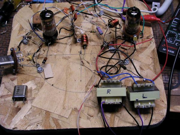
Figure 10
The receiver used for testing is a Sony ST-JX450A which contains decoding circuitry for all five of the originally proposed AM stereo systems, and has both narrow and wideband IF. Using the wideband setting, the audio bandwidth is 8 kHz, which barely qualifies as hifi, but is certainly better than most AM receivers, and more than adequate for most current AM broadcasters.
Once the circuit had warmed up, the cathode resistance of V1b was adjusted to give a grid bias of -2.5 volts. I had no means of measuring the linearity of the phase shift, but the -2.5 volts indicated in Figure 8 does indeed seem to give the best quality. The L+R signal going to the envelope modulator must be attenuated to a certain extent in order to remain in correct balance with the L-R signal going to the phase modulator. Initially a potentiometer was used, but eventually replaced with a simple fixed pair of resistors.
So how did it sound? Truthfully, it was far better than I expected. The stereo separation is very good, and under most listening conditions distortion is inaudible. The worst case scenario is when there is only a single input channel present. I tested this by unplugging the left input, leaving only the right input source. On the receiver I didn't notice any distortion on the right channel (or possibly very minimal), but the left channel instead of going completely silent, exhibited some faint but noticeable distorted sound. I repeated the test by unplugging the right channel input while leaving the left input source playing. The effect was the same. At the very least, one can say that the distortion problem is symmetrical, which seems to indicate that the phase modulator is at it's optimum setting. Aside from the dead channel test, I found the audio quality of the received signal to be excellent.
I've created two mp3 audio clips. They are exactly as received on my AM stereo receiver. I encountered some interference on my receiver while making these. However, after I recorded the first clip, I managed to adjust the receiver's loop antenna to minimize the noise. So, the second clip is cleaner.
The first is a swing band audio clip that has good stereo separation:
Johnny Favourite Swing Orchestra
I deleted a large chunk in the middle. Towards the end, I unplugged the Right audio input to the transmitter for a few seconds, then plugged it back in and unplugged the Left audio input. You can hear some noticeably distorted audio on the unplugged channel. This doesn't surprise me; I expected the worst distortion would occur when there was only one channel present.
The second clip is some electronica with some interesting sounds that pan left and right:
There was, however, one anomaly (which can be heard in the clips). Audio, which should have appeared exactly centred between the speakers, was shifted slightly to the right. I puzzled over this for some time, trying to figure out what might cause this. I considered and then dismissed the following possibilities:
- Imbalance in the audio matrix circuits;
- Self-modulation of the phase modulator due to the high level input signal;
- Non linearity of the phase modulator;
- Misadjustment of the antenna matching network.
The last item did in fact have some influence on the anomaly. By tuning the antenna slightly off peak, it was possible to shift the displaced audio back towards centre, but it didn't fully correct the problem.
At that point I decided the only way to solve the problem was to try to calculate (at least qualitatively) what kind of RF signal would produce this effect in the receiver. From the discussion given above with the vector diagrams, obviously what should be a flat "I" vector (In-Phase) had a slight bit of vertical ellipticity due to a constant phase shift every cycle. I concluded that this would manifest itself as an assymmetric (ie, distorted) carrier waveform. This made sense. The output signal at the plate of the crystal oscillator looks more like a sawtooth than a sinewave. Obviously, this needed to be cleaned up.
Also, even though I had initially dismissed the possibility that self-modulation of the phase modulator could be the cause this problem, I now realized that it could indeed be the cause, or at least be a contributing factor.
I decided, as a first approach, to try to clean up the carrier waveform. I tried a number of different things. I considered taking the signal from the tank circuit rather than the plate. However, this didn't produce enough signal and caused unstable oscillator operation. In the end a simple LC low pass filter between the oscillator output and the phase modulator input resolved the problem. There still remained a very slight mis-centering of the received audio, but it was easily corrected by a minor adjustment of the transmitter's antenna matching network. Therefore, I felt that no further action was required. I was rather relieved that I didn't need to address the possibility that the phase modulator was self-modulating.
Having resolved the main technical problems, I decided to turn my attention to building a 25Hz pilot tone generator. This was a far more formidable task than I'd expected. That will be discussed in the next part, at which time I will also present the final (or, at least, latest) schematic diagram.
To thank the Author because you find the post helpful or well done.
Part IV - Pilot Generator
I had assumed that having got the main part of the stereo transmitter working, the addition of a 25Hz pilot tone generator would be nearly trivial. Well, I was wrong. Having self-imposed the requirement to use vacuum tubes made things a bit trickier than I'd anticipated.
(For those of you who are reading this series of posts as a classic three act tragedy, you may want to consider this post to be the comic relief part. And certainly not because of any intention on my part at the outset.)
I originally had three possibilities:
- A circuit synchronized to the power mains frequency;
- An electromechanical generator using a synchronous motor locked to the power mains frequency;
- A circuit using something other than the power mains frequency as a standard.
Synchonizing to the power mains is very appealing because it is the most readily available frequency standard and cost practically nothing in terms of electronic components. If I lived in a country where the mains frequency was 50Hz, this would be probably have made things quite a bit easier. A simple frequency divider using neon lamps wound accomplish the task very simply. Unfortunately, the power frequency in North America is 60Hz. It would require a 5x frequency multiplier to get 300Hz and then a divide by 12 circuit to get 25Hz. A method of doing this with one tube didn't immediately spring to mind.
The electromechanical option is probably the route I would have taken if I'd had the components at hand. This would require a small synchronous motor, such as an electric clock motor, running at 300 RPM (5 rev/second). Then a small wheel would be attached to the motor shaft. The wheel would have 5 targets attached. These targets could be either magnetic or optical. A fixed pickup of the appropriate type (photo or magnetic) would then pick up the signal and pass it on to the rest of the circuit. Because of the low voltage levels required for the pilot signal, it shouldn't be necessary to add any amplification stages. But, for the lack of a suitable motor, I abandoned this idea. (Well, not really. If I ever manage to get a 300 RPM synchronous motor, I'll resurrect this sub-project.)
All that remains then, is the purely electronic circuit using some type of self-contained frequency standard. The list of options is:
- Piezoelectric Crystal;
- Tuning fork;
- LC tuned circuit;
- RC tuned circuit.
Bear in mind that because of the requirement for minimum number of components, using a high frequency reference and then dividing down the frequency, as is commonly done with monolithic circuits, is pretty much out of the question. Therefore, the frequency standards must operate at 25Hz.
A 25Hz crystal would have to be brought in by a special truck and would cost more money than I can ever dream of having. Idea officially crossed off list.
The tuning fork idea seems interesting. I could probably hammer something together in my workshop to do this, but I was, by this time, losing patience, and wanted to get something together. This leaves only the purely electronic approaches.
At this point I turned to an often used resource. I decided to search the Internet, and steal someone else's circuit. My brief Internet education on low frequency oscillators left me with the notion that an RC oscillator was the best way to go, as LC oscillators required unwieldy inductors. The two most popular circuits are the Wien bridge, and the Twin-T. The Wien bridge appeared to be the best circuit by most accounts, and if it was good enough for Mr. Hewlett, it was good enough for me. Unfortunately the Wien bridge gives a 360° phase shift in the feedback loop, thus requiring two tubes. Tubes don't grow on trees. Hence, idea officially crossed off list.
A Twin-T was the next circuit considered. I even found several vacuum tube versions, on the Internet, operating in the audio range. Unfortunately, after making the appropriate component adjustments, none of them wanted to operate at 25Hz. Idea officially crossed off list.
Unwieldy inductor or not, I decided to try an LC tuned circuit. Digging through my parts box, looking for an unwieldy inductor, I found instead, a small power transformer, Tamura 3FD-256. This transformer has dual 120V primary windings and dual 28V secondary windings. I measured the primary inductance on my $12 LC meter. For twelve dollars you don't get a lot of accuracy reading large inductance values. But from the reading, I inferred that the true inductance was somewhere between 12H and 100H. I guessed that the most likely value was nearer to the low end of the estimate. Accordingly, a resonating capacitance could be had without resorting to electrolytics. I tried several configurations but eventually arrived at the circuit shown in Figure 11.
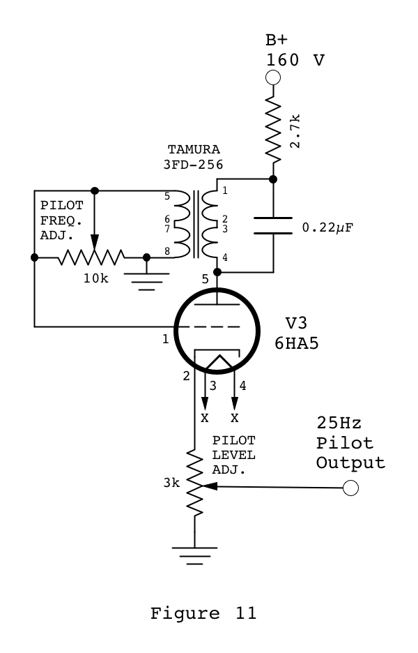
The choice of the 6HA5 triode was entirely due to the fact that I had some on hand.
The real problem with very low frequency LC oscillators is that tuning them is a major ordeal. I recall that early electonic organs, in their tone generating oscillators, used iron core inductors with a variable air gap. The gap was adjusted by means of small screw. Such an arrangement would mean lifetime employment for an organ serviceman. I wanted to avoid variable inductors. And, at this frequency, variable capacitors were out of the question.
The approach that I used was to provide sufficient capacitance across the inductor (0.22µF in the diagram) to bring the frequency within a Hertz or two of the target, but on the low side of 25Hz. Then by applying a variable load on the secondary of the transformer (the 10k pot), it would vary (i.e. decrease) the inductance on the primary side. Hence, the fine frequency adjustment could be accomplished using a variable resistance.
I had initially thought to have the transformer's low voltage winding in the plate circuit, and then have the tuned high voltage winding on the grid side. This proved unsatisfactory however, and so the HV side was connected to the plate, and the LV side to the grid.
The cathode resistor was chosen to be the largest value that still allowed the circuit to oscillate reliably. My thoughts were that the lowest plate current would give the lightest loading to the tuned circuit and the most stability. In operation, the cathode runs at about 7.5 volts for a plate current of 2.5mA.
I suddenly realize that I've presented a number of posts on this transmitter without including a single scope trace. I will rectify that now. Figure 12 shows the output of the 25Hz pilot generator.

Figure 12
This waveform is taken at the cathode. It's far from a perfect sinewave, but it's nothing that a low pass filter can't fix. So, I added the two pole filter as shown in Figure 13.

I should also mention that the output of the oscillator is taken off a potentiometer in the cathode circuit. The required signal level is very low, and this seems to be a suitable place.
After initial frequency adjustment, the oscillator seems to be quite stable. A few seconds after warm-up it was running at 24.9Hz. I checked the frequency every few minutes for the first half hour, and then sporadically for the next couple of hours. The frequency stayed at 24.9 the entire time. So, I'm cautiously optimistic that this oscillator circuit will be sufficiently stable. Only time will tell.
Although I'd promised it here, an updated complete transmitter schematic will be posted in the next instalment, along with some miscellaneous details and comments on things which were overlooked in the previous posts.
Comments, suggestions, ridicule, etc., are always welcome.
To thank the Author because you find the post helpful or well done.
Part V - The final Circuit
I delayed posting the "final" schematic diagram because during the testing of the transmitter I made a list of several things that I wanted to check out before locking things down. That work is now complete. Though there's always the possibility of making future changes, the circuit as it stands right now is fully functional and performs well. On that note, the schematic is presented here.

(Click on schematic for larger version.)
The breadboard (Figure 15) is now more cluttered due to the pilot generator which takes up the lower left quarter of real estate.

Figure 15
The most important change in the circuit, however, is the addition of an LC low pass filter between the crystal oscillator output and the input to the phase modulator to clean up the signal waveform. It consists of the 680µH inductor, the 22pF capacitor and the 2.2k resistor near the plate of V1a. This is the change that resolved the off-centre sound problem.
I should also mention that while I was debugging the off-centre sound problem I considered the possibility that the problem might be due to the modulator tube V2b running in Class C. To check this out, I added a cathode bias resistor and bypass capacitor. But it made no improvement. So I removed it. Upon further rumination, I've concluded that while even harmonic distortion of the carrier is the root cause of the problem, the phase relationship between the fundamental and the 2nd harmonic is what determines the shift in sound, left or right. Therefore, I've concluded that 2nd harmonic distortion can be tolerated as long as it has the correct phase relationship with the fundamental. I believe that if there is any self-modulation happening in the phase modulator, it may be possible to balance this out by making deliberate use of the 2nd harmonic distortion in the carrier with a suitable phase shift network to adjust the phase of the harmonic to cancel out the self-modulation in the modulator. It was just an interesting thought, mind you. I have no intention of redesigning the oscillator/phase modulator at this point. It works fine as it stands.
On the topic of harmonic distortion of the carrier, odd harmonic distortion should cause no problems.
Some other minor circuit changes were made:
The 2.5mH choke in the cathode circuit of V1a was replaced with a 2.2k resistor. The resistor works just as well and is cheaper and easier to obtain.
The 2.2k resistor in the cathode of V1b was replaced with a 2.5k pot. This allows convenient adjustment of the bias voltage to the best operating point. Note also the 100µF bypass capacitor. This is much larger than what is normally used. However, the cutoff frequency must be below 25Hz because of the presence of the 25Hz pilot tone. In addition, the 100µF bypass capacitor is bypassed with a 0.05µF film capacitor to avoid any problems due to increased impedance of the electrolytic at high frequencies.
Setup Notes
In getting the transmitter into operation the sequence of operations was generally as follows:
- Apply power and allow the transmitter to warm up for a few minutes.
- Apply audio signals to the transmitter inputs.
- Adjust the antenna matching network to obtain the maximum output power. This is an iterative combination of adjusting the variable capacitor and the variable inductor. My inductor is not fully adjustable. It has a number of fixed taps that cover the range shown on the schematic. This works well for my 3 meter long antenna.
- Adjust the audio input levels for a good sounding signal on the receiver.
- Adjust the bias on the phase modulator to 2.5 volts, as measured at the cathode of V1b.
- Adjust the pilot signal frequency to 25Hz ±0.2Hz.
- Increase the pilot level until the receiver goes into stereo mode.
- Readjust the capacitor on the antenna matching network to get the received audio correctly centred between the speakers.
At this point the transmitter should be functioning properly but may require some of the adjustments to be rechecked and readjusted as necessary.
L+R/L-R Balance Adjustment
During testing, the voltage divider in the L+R line consisting of the 3.3k and 1.5k resistors was replaced with a 5k pot. I had earlier used the 5k pot to set the balance between L+R and L-R by ear. I had simply started with the pot set for maximum L+R signal, and then with music playing, slowly decreased it until there was no audible improvement in stereo separation. I then measured the pot setting and then installed the equivalent fixed resistors.
This time, I decided to do a more scientific adjustment. I applied a 600Hz tone to the left channel only (right channel silent). Then listening to the receiver, I adjusted the pot for minimum volume on the right channel. I made note of the pot setting and I then repeated the test with the tone input to the right channel and readjusted the pot for minimun volume on the receiver's left channel. In both cases the pot setting was the same, as it should be. I should mention that it was not possible in either case to completely null out the audio, but it was substantially reduced.
The result of the more scientific L+R/L-R balance adjustment is that for best stereo separation, the 3.3k resistor should be replaced with a 5.1k resistor, and the 1.5k resistor should be replaced with a 680 ohm resistor. This means that the input source level must be increased to compensate, but a line level audio signal is still more than enough to give full modulation of the transmitter. I show these values in parentheses in the schematic. The truth is that when normal music is playing, it's nearly impossible (at least to my ears) to tell the difference in separation between the two different sets of voltage divider values.
Figure 16 shows a photo of my receiver setup, receiving an AM stereo signal from my transmitter. Note, the red stereo LED is lit up. The receiver is a Sony ST-JX450A.

Figure 16
Missing Channel Distortion
During the balance adjustment, I noticed a major improvement over the earlier sound tests. In the first audio clip posted in Part III, there was significant distortion in the "inactive" audio channel. After installing the LC low pass filter between the oscillator and the phase modulator, this distortion is now reduced to the point that I'm unable to hear it.
Operating Frequency
There are a few frequency dependent components in this circuit. Therefore, if it's to be operated at different frequencies, minor attention needs to be given to these parts. Except for the antenna matching network, these are all located in the plate circuits of V1a and V1b. They include the two reactance capacitors Xc and the LC low pass filter components: the 680µH inductor and 22pF capacitor.
I based my design on an operating frequency of 1500kHz. I have both a 1480kHz crystal and a 1520kHz crystal, and use whichever frequency has the least interference at the moment. The testing was done using the 1520kHz crystal.
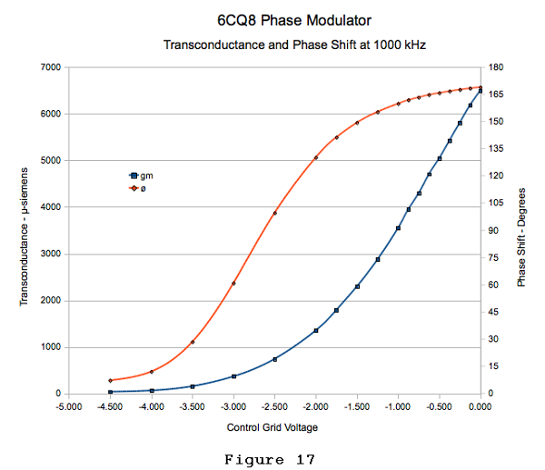
The dependence of Xc on operating frequency is not as signifcant as one might expect. I have repeated the phase shift chart in Figure 17 using the same 100pF capacitors, but at an operating frequency of 1000kHz. The curve shifts a bit to the left, but remains the same shape. Therefore, it is sufficient merely to readjust the V1b cathode bias from 2.5 volts to 2.8 volts. Or for that matter, do nothing at all; the difference isn't audible to me. Likewise, at an operating frequency of 1700kHz, the new bias setting is 2.4 volts. Not enough to worry about. Of couse, if the transmitter is being designed for a specific frequency, it's worthwhile to pick the capacitors so that they have a reactance of about 1000 ohms at the operating frequency.
The low pass filter consisting of the 680µH inductor and 22pF capacitor is similarly non critical. It's there to remove second harmonics of the carrier frequency. I tested the receiver at 1000kHz and found no need to make any component changes.
One other thing I wanted to test, was the use of a ceramic resonator in the oscillator in place of the crystal. I had used resonators in my other transmitters, and they worked well. I was a bit concerned that there may be some interaction between the phase modulator and the oscillator, that might detrimentally affect the stability of hte oscillator. However, this was not the case. The transmitter worked just as well with the ceramic resonator as it did with the crystal. The only changes that were required were in the oscillator feedback divider capacitors. The 22pF capacitor was replaced with a 150pF capacitor, and the 100pF capacitor was replaced with a 5-150pF trimmer which was needed to fine tune the frequency. (I found that the oscillator could be as much as 5kHz off frequency, and the receiver was still able to receive and decode the stereo signal.)
Pilot Generator
After running the transmitter for many hours over the past few days, I've found the pilot generator to be very stable. The variable resistance gives very fine frequency adjustment over the range of 24.4Hz to 32 Hz. The adjustment is non linear, with the frequency changing faster as the resistance decreases. However, most of my adjusting was at the high resistance end of the pot, so adjustment was quite painless. (I briefly experimented with an audio taper pot, but didn't find it to be much better.)
The only annoyance is that my HP 5381A frequency counter takes 10 seconds per update at it's highest resolution. I briefly entertained the idea of using Lissajous figures on the scope to set the frequency relative to the local 60Hz line frequency. Unfortunately this would require 5 cycles of the 25Hz signal before the pattern repeats, requiring 0.2 seconds per update. The result (Figure 18) was a badly flickering display (with 12 peaks to count) and was reminiscent of a green laser light show during a drunken evening at the disco club. My head spins at the memories.

Figure 18
Bonus Question for Alert Readers: By examining Figure 18 closely, and assuming that the vertical trace is exactly 60Hz, is the horizontal signal slightly above, or slightly below 25Hz?
(Answer at bottom of post.)
In contrast, this would be easy with a 50Hz line frequency which would produce a simple figure-8 pattern. Alas, a frequency counter remains the only practical way for me to adjust the frequency.
Regarding the pilot tone, it can be seen from the schematic, that it is added to the L-R signal to modulate the phase of the carrier. It never appears in the amplitude modulation. So, this would never be audible on a monaural receiver. In a stereo receiver the pilot tone is filtered out. It doesn't interfere with normal low audio frequencies, because, by their nature, the low frequencies are non directional and don't tend to appear in the L-R signal. Hence there is no loss of audio information by this low pass filtering.
According to C-Quam specifications, the level of the pilot signal is 4% of the total audio. I simply set it by finding the minimum level that reliably triggered the receiver's stereo mode, and then increased it slightly, for a margin of safety.
One thing to bear in mind however, if the audio input signals to the transmitter are excessive, I've found that the receiver will lose the pilot signal and drop out of stereo mode.
6CQ8 Substitutes
I originally selected the 6CQ8 as the tube of choice for my earlier transmitter because it was listed as having a tetrode section, which was expected to give better screen modulation than a pentode. However it was pointed out to me by Tom Bryant, that the 6CQ8 has a number of recommended substitutes listed for it, and they are all identified as pentodes rather than tetrodes. Tom examined several of the different tubes and said they appeared to be identical in structure. He kindly sent me a sample of several of the different tubes. I examined them closely (Figure 19) and confirmed what he'd already told me.

Figure 19
These tubes are identical in every respect. They are all beam tubes in fact. They all have a very clearly visible set of beam forming plates which are internally connected to the cathode. I have tried them all in this circuit, and they function with no other circuit changes. Here is the list of equivalent tubes:
- 6CQ8
- 6GH8A
- 6U8A/ECF82
- 6KD8
Audio Input Sources
For my testing, my audio signal source has been a CD player with line level outputs connected through a small mixing board which allows me to adjust the audio input level to the transmitter. For this arrangement, the input transformers in the transmitter each have their two primaries wired in series to give a 600 ohm impedance. If this were to be operated from a portable MP3 player, it would be advantageous to wire the primaries in parallel (or just use a single winding) to reduce the impedance to 150 ohms which is a better match for the MP3 player's headphone output, and would give more input signal to the transmitter.
- Large Schematic (78 KB)
To thank the Author because you find the post helpful or well done.
Counter, Phase
Fascinating.
> my HP 5381A frequency counter takes 10 seconds per update
What you want is a period counter. Start a 1MHz counter. Gate it with the rise of the 25?Hz tone. 40,000 counts is 25Hz. The answer can be available in 1/25th of a second.
Nixie tubes can count at 10KHz which suggests 0.25% resolution without transistors. (Vacuum tubes sure can decade-count but it takes a lot of power.)
> the Wien bridge, and the Twin-T
There are a million or more 6Hz-15hz Phase-Shift tube oscillators used for "vibrato" (truly tremolo) in guitar amplifiers. One quaint example is top of Fender Tremolux 5E9A.
Phase-Shift oscillator needs loaded gain over ~~29 to cover its losses. In practice, 12AT7 Mu=60 seldom works, 12AX7 Mu=100 usually works but not always. This may foil "Cinderella tube" design (although 6AU6 as pentode has been done).
Take output from the plate as shown; this is the cleanest point. I suspect you do not need so much drive current and can omit the cathode follower.
Frequency can be shifted almost 2:1 with 10:1 change of one resistor and plenty of excess gain, so +/-10% is trivial. Amplitude is of course to-clipping and even after a low-pass you can have many-many Volts. Frequency does shift with operating point, slower when clipping is significant. For stability you bias to just-barely start, so the least clipping will stabilize the amplitude. (In guitar-amp you need quick-start, excess gain isn't quite enough, this plan has a 10Meg "kick-start" off the foot switch.)
I'm not at all sure this can hold 0.2% frequency stability... is the decoder that fussy?
To thank the Author because you find the post helpful or well done.
Re: Counter & Phase shift oscillator
Hi Paul,
Thank you for your comments.
I assume that most modern frequency counters automatically switch to time interval mode for low frequencies. When I bought the HP 5381A I hadn't expected to use it for such low frequencies.
Edit: I just realized that my digital multimeter has a frequency measurement capability, reading Hz to 2 decimal places, and updates very quickly. Certainly won't be as accurate as the HP counter, but adequate for this job.
It never occurred to me to look at tremolo circuits. Thanks for pointing them out. I did briefly consider a phase shift oscillator, but because of the gain requirements, I figured one of the other configurations would be easier to implement.
Joe Sousa also mentioned in an email, that the Wien Bridge can be built using a dual control pentode, making use of the non-inverting G3-G2 gain. I see that he's now posted a detailed writeup of it.
I'm not sure how fussy the decoder in my receiver is about pilot frequency. The receiver uses a proprietary Sony decoder chip. It seems to be happy with ±0.5Hz. The datasheet for the Motorola MC13027A decoder (which is my only source of information on pilot frequency accuracy requirements) shows an allowable range of 24.4 to 25.6 Hz. My LC oscillator is able to maintain ±0.2Hz without a regulated power supply, so I'll probably stay with that circuit now, (especially since I've already got most of it installed in the final chassis).
To thank the Author because you find the post helpful or well done.
Part VI - Final Assembly
Perhaps no one was expecting a Part VI.
Well...Surprise!
And I'm sure no one is more surprised than I am, considering the fiasco of putting the transmitter into a cabinet. But, I'll spare you from most of the unpleasant details.
It took some time to transfer the sloppy breadboard experiment into a final completed project, but the following photo (Figure 20) shows the final result.

Figure 20
While the front panel controls weren't entirely necessary, it's no fun building an electronic device without having a few knobs to twist. The controls from left to right, are:
- Stereo Separation Adjustment,
- Multi-function Meter,
- Pilot Level Adjustment,
- Pilot Frequency Adjustment.
Along the bottom, from left to right:
- Meter function switch
- AC Power Lamp
- Power Switch
The antenna output is the 5-way binding post on top of the chassis behind the leftmost tube. Audio input jacks are on the rear panel.
Access holes in the top of the chassis allow adjustment of the antenna tuning coil, oscillator crystal trimmer, and phase modulator bias.
Some of these controls do not appear in the schematic which was posted earlier. I will discuss these below.
I constructed the chassis from a piece of 0.5mm galvanized steel. This is a bit on the thin side, and subject to warping. As a result, it wasn't appropriate to have a high gloss finish. So, I used a textured matt "Stone" finish paint (Figure 21).

Figure 21
To minimize the number of holes visible from the top of the chassis, I soldered the terminal strips in place (Figure 22).

Figure 22
Because the chassis is quite compact, I set out to pre-assemble as many things as possible before installing in the chassis. Figure 23 shows the power transformer, power line filter, B+ rectifier and filter, and tube heater wiring.

Figure 23
Because the audio and pilot oscillator transformers were designed for printed circuit mounting, it was most convenient to build several pre-assemblies using veroboard. These are shown in Figure 24, along with pre-assembly for the crystal socket (made from a 9-pin miniature tube socket), and the mounting bracket for the antenna tuning coil.

Figure 24
Figure 25 shows the chassis with the power transformer, B+ supply, tube sockets, and antenna tuner installed.
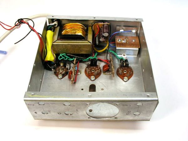
Figure 25
Components which needed to be wired between the tube sockets and the terminal strips were installed next, followed by the crystal socket assembly, and finally, the transformer assemblies and front panel controls (Figure 26).
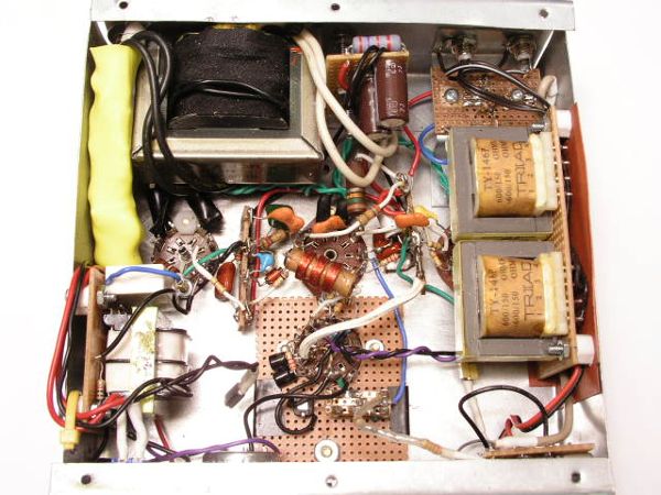
Figure 26
Circuit Changes - Again!
The transmitter would have been done sooner, except for two faulty components which were discovered after most of the chassis was wired. The power transformer appeared to have a faulty winding, and was running hot. Fortunately, I had a replacement on hand. Also, one of the 5kΩ potentiometers was intermittent. It only became evident once the mounting nut was torqued down on the bushing. I didn't have a spare 5k pot, but since the stereo separation pot value isn't critical, I substituted a 10kΩ pot.
Also, while building the final version, I made a few minor changes to the circuit, which I will discuss now. These changes are reflected in the revised schematic which should be referred to in the following discussion.

(Click on schematic for larger version)
a) RF Oscillator
The first change was to install a trimmer capacitor in the capacitive divider in the crystal tank circuit. While sorting out the second harmonic distortion problem, it occurred to me that the relative phase of the second harmonic could possibly be adjusted to completely eliminate the shifted centre channel problem. As well, a trimmer would be required when using a ceramic resonator. So, I put it in. It appears to have helped the second harmonic problem somewhat, but didn't fix it completely, so the final centre channel shift must still be trimmed with the antenna tuning.
b) Antenna Matching Network
The second change was to revise the antenna matching network. Originally, I had an RF choke in the plate of the output tube, and then the plate was connected to the antenna through an L-network. The L-network had started out as a pi-network, but with the short antenna, the second variable capacitor was unnecessary. I did a bit of rudimentary research on electrically short antennas, and concluded that it would be best to eliminate the plate choke replacing it with a parallel resonant plate circuit. This eliminates the losses due to the relatively low Q of the RF choke. The short 3 meter antenna is very inefficient, and it's important to eliminate as many losses as possible.
My brief research of short antenna theory led me to the following formulae for monopole antennas:
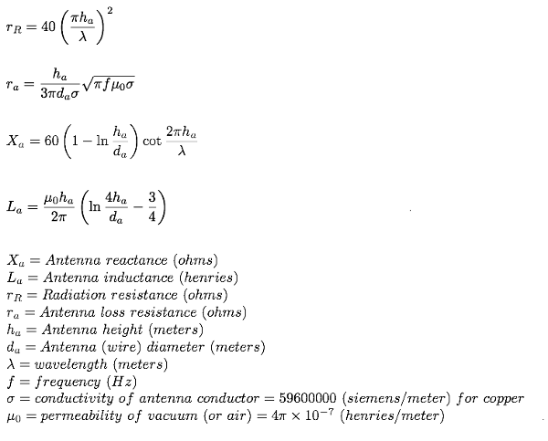
This took quite a bit of digging. Just about every formula I found on the Internet, contained obvious typos, and it was only after reviewing a number of different documents that I pieced together the above formulae. There may still be errors in them. So, take heed.
Assuming the antenna is a vertical monopole with a ground plane (which is a stretch of the imagination, but this is the closest simple model), the radiation resistance at 1500kHz for a 3 meter high antenna is approximately 0.09Ω, and assuming the antenna is made of #12 AWG wire (2mm diameter), the AC resistance is about 0.05Ω (the formula includes a factor of 1/3 to account for linearly decreasing current over the length of the antenna). So, without even considering the losses in the ground system, over a third of the RF energy put into the antenna is lost due to AC resistance caused by skin effect. At the same time the reactance for the modelled antenna is -j4kΩ. Fortunately, reactance can be compensated for with an appropriate matching network. The antenna reactance corresponds to a net antenna capacitance of about 24pF. (Inductance is about 4.7µH contributing an insignificant +j44Ω.) Because of this antenna capacitance, it's counterproductive to add more capacitance in parallel with the antenna, as this would just split the current that should all go to the antenna. So ideally, the plate circuit would consist of just enough inductance to resonate out the antenna capacitance. If a fixed inductor is used, then the value chosen is generally slightly smaller than necessary, and then a variable capacitance is added in parallel to bring things back into resonance. By using a variable inductor of the correct range, the additional capacitance is unnecessary. I found a small oscillator coil from a transistor radio which was in the correct range to resonate with my antenna (100-250µH), and it didn't seem to mind the B+ voltage that was impressed across it. Testing with a simple field strength meter confirmed that the variable plate inductance was more efficient at getting power into the antenna than the original L-network. The parallel network also acts as an impedance match between the high resistance plate circuit and the very low resistance antenna. At resonance the parallel LC network appears as a very high impedance to the plate circuit, while at the same time, the high circulating currents put maximum RF current into the low resistance antenna. I should acknowledge at this point that the monopole antenna model with a reactance of -j4kΩ would indicate that the resonating inductance should be about 470µH rather than the actual 175µH. However, considering the approximations that were made in the analysis, I'm pleased that the numbers are the same order of magnitude.
c) 25Hz Pilot Oscillator
Not being able to leave things well enough alone, I decided to have another look at the pilot oscillator. This was prompted by the discovery that I had inadvertently left a DC path between the cathode of the pilot oscillator and the grid of the phase modulator tube. While this didn't affect operation of the transmitter, it did make the set-up adjustments a bit complicated since, changing the pilot oscillator output level would alter the phase modulator bias, and vice versa, making it an iterative process. Hence, I decided to have another look at it. I was tempted to try a Wien Bridge oscillator circuit based on Joe Sousa's 6AS6 design, and indeed I built the circuit. However, I found it to be more susceptible to power supply ripple than the LC circuit which I'd been using. So, I stayed with the LC oscillator, but changed the feedback from the plate to the cathode. I'm not sure why I didn't do this right from the start; I've always had better results with cathode feedback. With the low impedance cathode feedback, I was able to put the tuned circuit on the grid side, and spare one transformer winding which I could now use for the output. Since this has no DC bias on it, I didn't have to add any blocking capacitor, which at 25Hz would be rather large, and in previous testing led to instability in the phase modulator. This feedback change along with some changes in biasing, resulted in a much better looking waveform. The signal output, while still not a perfect sinewave, is now symmetrical and much lower in distortion (Figure 28). Thus, I was able to eliminate the low pass filter. I've found that the relationship between oscillator frequency and transformer load resistance is reasonably linear as long as the resistance goes no lower than about 1kΩ. Consequently, I added a 1kΩ resistor in series with the 5k frequency adjust pot, and now have quite acceptably linear adjustment over a range of 25 Hz ±3 Hz. (Because of the narrow range of adjustment, the resonating capacitor shown as 0.22µF, had to be hand picked to get the oscillator into the correct range.)

Figure 28
Finally—another change—the pilot oscillator signal was combined in series with the L-R signal rather than the previous parallel arrangement. This eliminated a couple of resistors, and increased the overall drive level to the phase modulator, with the result that full modulation requires less audio input signal than before.
d) Stereo Separation Control
As I'd mentioned in an earlier post, I've flip-flopped back and forth whether to have a potentiometer or a fixed voltage divider. The answer is that a fixed divider, once set, is perfectly acceptable, but I had space on the front panel of the transmitter, and so I added the stereo separation control back into the circuit. In the original breadboard circuit, I'd used a 5k pot, but as mentioned earlier, it proved to be defective, and my only spare was a 10kΩ pot. The final schematic shows the value as 10kΩ, but it's not critical.
e) Multi-Function Meter
I had this little 100µA meter in my junk box waiting for a project. I decided it would be useful in setting the phase modulator bias, and also as a power output indicator. Before I was finished, I'd also added an audio input level function, which is of questionable utility, and may need a bit more engineering.
The meter has an internal resistance of 2500Ω, so that with the addition of a 27k series resistor (Selector Switch set to Input A), the meter will read 0-3 volts DC which is suitable for setting the phase modulator bias.
In position B, the rectified L+R audio signal excites the meter. The forward voltage drop across the 1N5711 Schottky diode is about 0.3 volts, and this significantly affects the sensitivity to low level signals. But the meter is quite sensitive to signals that exceed this threshold, and since over-modulation doesn't appear to set in below the 0.3 volt level, I believe it will prove useful in monitoring input level. The main drawback is that it doesn't behave quite like a normal VU meter, and so, it will take some getting used to. If it proves unsatisfactory, I may try substituting another Schottky diode with a lower forward voltage.
In position C, the meter reads radiated signal strength. In this setting, the meter is wired exactly the same as the external signal strength meter that I've been using to adjust the antenna matching network. Now having this built in, is probably the most useful purpose that the meter will be put to. The pair of 1N34A diodes, near the antenna output, pick up and rectify the RF, and the level is indicated on the meter. The pickup probe is just a short piece of wire in close proximity to the antenna output jack.
I think I've pretty much flogged this thing to death now, but as always, comments and questions are always welcome.
(Edited to add pilot signal scope trace, and to revise antenna formulae.)
Attachments:- Schematic Diagram - As Built (149 KB)
To thank the Author because you find the post helpful or well done.