ECH81Curve traces
ECH81Curve traces

Fellow Radiophiles,
In recent discussions with Jacob Roschy, it has become apparent how popular and versatile the ECH81 tube is. Jacob has used it in many of his transmitter and receiver designs. However, the extensive manufacturer's curves focus on the original intended application as Heptode-Mixer&Triode-Oscillator, or as Heptode RF amplifier.
I include here some additional curves that explore the behaviour of G3, which is normally used for local oscillator (LO) injection. This choice of grid requires a relatively wide p-p input for efficient mixing, but this is easily supplied by the independent triode oscillator. This leaves G1 independently available for RF input with remote cutoff. The nominal conversion transconductance is specified as 775uS.
Other Heptodes, such as the very common 6BE6/EK90, are designed for LO injection at G1 and RF input at G3. In the self-oscillating configuration, the nominal transconductance is 455uS, and up to 600uS with a heavy 1mA separate LO injection into G1.
Some of the advantage of the ECH81 is the higher transconductance of RF input grid.

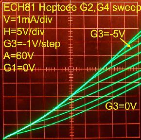
Comparing the effect of the control grid G1 on plate current to the effect of the LO injection grid G3.
G2=G4=60V
The third photo was taken with 5V/div horizontally.


Comparing the effect of control grid G1 with LO injection grid on G2-G4 Screen currents. Note the non-inverting voltage gain and negative transconductance from G3 to G2-G4.


G2=G4=120V. This is the nominal recommended screen bias. Note how much higher the gm1=<4.6mS is than the gm3=<1mS. This is even more so, near 0V bias for either grid.


The very modest gm3 has hardly any effect when added to gm1 by driving both grids simultaneously as seen in the next photo.
The photo on the right was done with -2V/step at G3. Note how sudden and sharp it's cutoff is with -18V at the lowest trace.


The following curves were done with reduced G2=G4=30V screen voltage with particular application to the little Luis Freixa Periquito radio I repaired recently.
Each column of the following 9 plots represents three source resistances driving the stepped grids: 0Ω, 100kΩ, 1Meg0Ω.
The first row shows the control of G1, the second row shows the control of G3 and the last row shows the simultaneous control of G1+G3 in parallel drive.
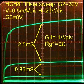

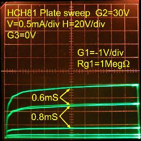

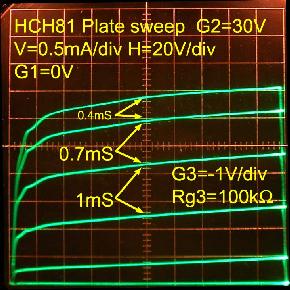

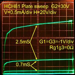
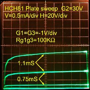
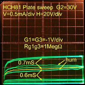
Note how severe the attenuation is at low control grid G1 voltages at 0V. The third grid G3 retains a high impedance down to zero volts as can be seen in the right-most column.
As was seen for higher voltages at G2=G4=120V, driving G1 and G3 simultaneously, as opposed to driving just G1, has little effect on the plate current with G2=G4=30V.
Regards,
-Joe
To thank the Author because you find the post helpful or well done.
Wow

Joe,
If ever I am having doubts about my lack of knowledge in the area of radio, I simply read one of your articles. Your brain is a scary thing indeed.
All joking aside, thank you for yet another informative and interesting article. Please 'keep em coming!'
Thanks again,
Bob
To thank the Author because you find the post helpful or well done.