eumig: DKE-38B DKE-1938B; Power connections
? eumig: DKE-38B DKE-1938B; Power connections

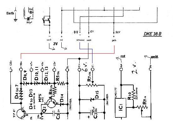
I have started working on my DKE38-B. This radio takes three input voltages, +90, +6, and +2. You'd think this should be pretty straightforward. However, looking at the schematic, I am confused. Look at the +6 volt lead (the "+ weiss" line) in the diagram below:
.jpg)
This appears to be connected directly to ground! Surely this cannot be. On the actual radio, this white wire has a little tag that says "+6 v". If I connect my power supply according to this diagram, I will short it out. Can anyone explain this apparent paradox? I want to be sure I don't make a critical error with this radio. Thanks!
To thank the Author because you find the post helpful or well done.
Grid bias

Dear Michele,
The +6V seems to be just a grid bias for the KL1 output tube. The connection is correct, since the positive lead to the chassis grants -6V on the grid. No switch is needed here, since the current falls to zero when the filament is not lighted.
Regards, Emilio
To thank the Author because you find the post helpful or well done.
Battery connections

Hello Michele
Emilio provided already the correct answer.
If you use other power supplies instead of a storage battery or dry cells for the plate voltage, make sure that the negative lead (- schwarz) is floating against ground! Otherwise you will indeed create a short circuit!
In the drawing, the +6V is connected to ground (Earth)!

To thank the Author because you find the post helpful or well done.
? AC power supply connections
Thanks to both Emilio and Wolfganga for their kind replies. I can see now how when connected using the two original batteries there would be no problem. However, here is the power supply I intend to use (this is the kit distrbuted by Antique Electronics Supply):
The problem is that it has three different grounds, one for each voltage. Here is how I'm thinking of connecting the five wires on the radio - is there any reason why this won't work? Will I damage anything doing it this way?
A+ on the power supply to Akku + (rot) (this is the +2V supply)
A- to Akku - (weiss)
B+ to +6V (weiss)
B- and C- tied together and connected to schwartz
C+ to +90V (gelb)
Thanks!
To thank the Author because you find the post helpful or well done.
Power Supply
Dear Michele
The copy of your PS schematic is difficult to read in details, so I made a new drawing merging things together.
This should be the best way:
To thank the Author because you find the post helpful or well done.
The solution
Thank you very much for your help, Wolfgang. While your diagram makes it completely clear, it appears to create a direct connection between the C+ terminal on the power supply and the A-. Both of these terminals are connected via the two weiss wires (which themselves are connected together).. Won't that create a dead short?
And I'm sorry about the scan. I do have a high quality scan that I intend to submit to RM as a new model but I had to reduce the resolution so it wouldn't be too big for a posting. And I didn't want to wait for the whole new model process before figuring out which connections I should make.
Hopefully I can get to performing some tests on the radio. The tubes all have filament continuity and the parts all appear to be original. This is my first battery radio and I want to be careful with it. DKE38-B's do not seem to be very common, at least n the US.
To thank the Author because you find the post helpful or well done.
Three separate voltages!
Hello Michele
You wrote:
..... it appears to create a direct connection between the C+ terminal on the power supply and the A-. Both of these terminals are connected via the two weiss wires (which themselves are connected
together).. Won't that create a dead short?
In the diagram given, we see two white leads, +6V (C+) and - 2V (A-). The latter is connected via the on-off switch to earth.
In the second diagram, the two weiß wires are themselves connected together and the on-off switch is wired differently. What is the reality?
Anyhow, we need both connections as depicted
Kind regards.
To thank the Author because you find the post helpful or well done.