Deutscher Kleinempfänger Batt. DKE-38B DKE-1938B
Eumig, Elektrizitäts und Metallwaren-Industrie-Gesellschaft mbH; Wien
- País
- Austria
- Fabricante / Marca
- Eumig, Elektrizitäts und Metallwaren-Industrie-Gesellschaft mbH; Wien
- Año
- 1939–1945
- Categoría
- Radio - o Sintonizador pasado WW2
- Radiomuseum.org ID
- 75358


Radio meiner Sammlung
Radio meiner Sammlung

Radio meiner Sammlung

Radio meiner Sammlung
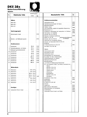
Haga clic en la miniatura esquemática para solicitarlo como documento gratuito.
- Numero de valvulas
- 3
- Principio principal
- RFS con reacción (regenerativo)
- Número de circuitos sintonía
- 1 Circuíto(s) AM
- Gama de ondas
- OM y OL
- Tensión de funcionamiento
- Baterías recargables o pilas
- Altavoz
- Altavoz magnético de membrana libre, sin suspensión.
- Material
- Bakelita
- de Radiomuseum.org
- Modelo: Deutscher Kleinempfänger Batt. DKE-38B DKE-1938B - Eumig, Elektrizitäts und
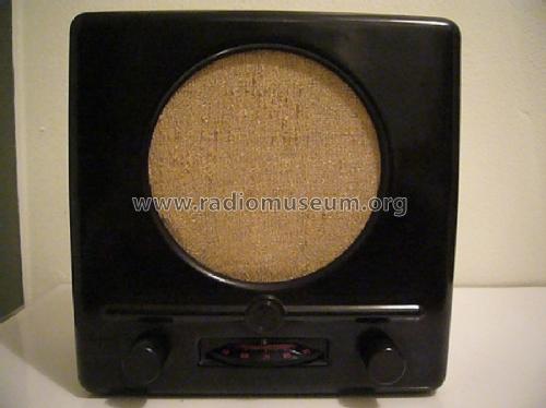
- Forma
- Sobremesa de tamaño mediano sin botonera <= 35 cm. (Incluso portables pero sólo con alimantación por red).
- Ancho, altura, profundidad
- 240 x 240 x 120 mm / 9.4 x 9.4 x 4.7 inch
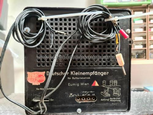
- Anotaciones
- Es gibt nur einen Batterie-DKE, aber zweierlei Rückwände: "DKE für Batteriebetrieb" sowohl mit als auch ohne die Jahreszahl 1938.
Siehe auch Deutschland. Normalerweise nur unter Gemeinschaftserzeugnisse geführt.
- Procedencia de los datos
- Radiokatalog Band 2, Ernst Erb
- Autor
- Modelo creado por Konrad Birkner † 12.08.2014. Ver en "Modificar Ficha" los participantes posteriores.
- Otros modelos
-
Donde encontrará 259 modelos, 229 con imágenes y 177 con esquemas.
Ir al listado general de Eumig, Elektrizitäts und Metallwaren-Industrie-Gesellschaft mbH; Wien
Colecciones
El modelo Deutscher Kleinempfänger Batt. es parte de las colecciones de los siguientes miembros.
Contribuciones en el Foro acerca de este modelo: Eumig, Elektrizitäts: Deutscher Kleinempfänger Batt. DKE-38B DKE-1938B
Hilos: 1 | Mensajes: 7
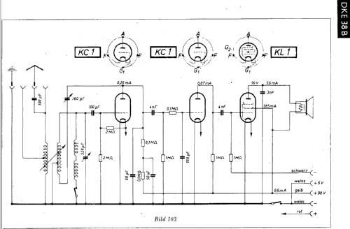
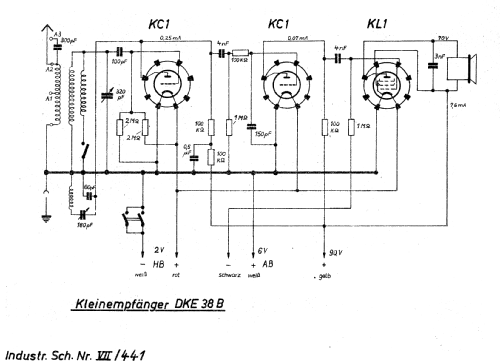
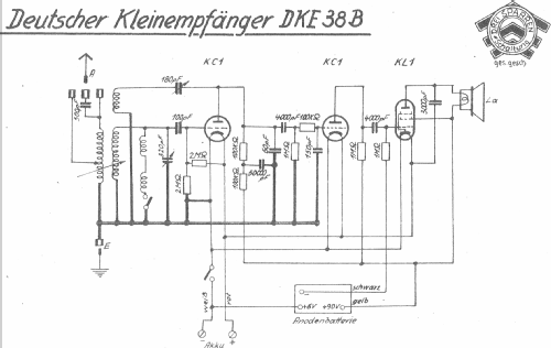
I have started working on my DKE38-B. This radio takes three input voltages, +90, +6, and +2. You'd think this should be pretty straightforward. However, looking at the schematic, I am confused. Look at the +6 volt lead (the "+ weiss" line) in the diagram below:
.jpg)
This appears to be connected directly to ground! Surely this cannot be. On the actual radio, this white wire has a little tag that says "+6 v". If I connect my power supply according to this diagram, I will short it out. Can anyone explain this apparent paradox? I want to be sure I don't make a critical error with this radio. Thanks!
Michele Denber, 16.Nov.10