For Beginners: Identifying Resistors
For Beginners: Identifying Resistors
First read Reading Schematics and Circuits Part 1
Then read Codes and Prefixes ...

Euro and USA symbols
Appearance of Resistors

Older style Body-tip-spot. Usually Carbon Composition. Very bulky compared to power rating
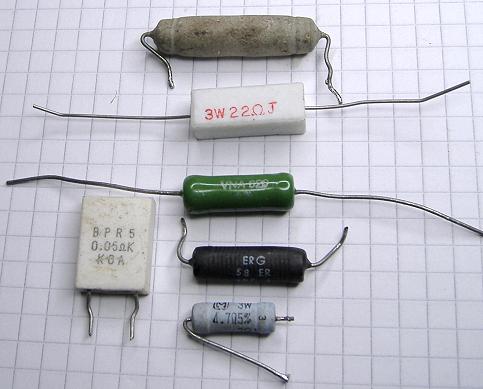
Wirewound Resistors used from 1W to 200W. But not for RF / IF applications due to inductance. Fine for Power / HT / LT rails and many Audio applications. Generally only 0.005 Ohms to 2 000 Ohms. 10 to 470 Ohms common. Often a Ceramic case or pottery glaze.

Carbon Composition (avoid), Carbon Film, Metal Film and Metal Oxide look like these. The top right 15K is a typical 1950s carbon composition in a ceramic tube (Silver =10%). It may be only 1/4W or 1/2 rating. The largest 15K (Gold = 5%) is a 1970s Carbon Film (Film on outside of rod, end caps and coated). The 1 Ohm (5%) is likely 1980s.
The three very small resistors on bottom left are typical of Modern (post 1990s) 1/4W Carbon Film 1/3W Metal Film or even 1/2W Metal Oxide (Though those are likely all Carbon Film bought in the last 5 years, the middle is 5% and the other two are 1%).
Variable Resistors
Also known as Potentiometers. It's not got a front panel knob it's a "preset" resistor.

These usually have the value written on the body with an A or B
B = Log (Logarithmic) law for Volume controls
A = Linear law
They can be rotary, ganged, concentric ganged, disk or linear slider.

Modern Miniature type with power switch.

Traditional Volume Control with Double pole On/Off switch. Vintage ones are larger and have a metal rather than plastic shaft (steel, alloy or Brass), either with partial flat, larger flat or no flat to stop knob slipping.

Single pole On/Off

Double pole switch, but push/pull for On/Off rather than minimum position. Printed Circuit board mount.

Full size "modern" pot for wire-wrap, PCB or solder. Solder lugs for single pole on/off switch.
Stereo will use a pair of Ganged "pots" on one shaft. Some sets use a pair of pots, but dual concentric shaft. An outer tube with two notches drives the first "pot" and a smaller inner shaft drives the rear "pot". Harder to source replacements.
Don't needlessly replace resistors. In many cases a few out by 30% isn't important. The output Valve / Tube cathode resistor must not be too low. More than 10% to 15% wrong, then replace it. Grid resistors can be 50% out and it won't make much difference. Screen and Anode resistors can be +/-20% with little significance.
Similarly replacing a 2M pot with 1M or 1M with 470K may be fine. You may have to increase a series capacitor feeding a pot if you reduce it more than 30% in value. It takes design knowledge to understand which parts have more critical values. The older pre 1940s or pre 1030s sets had less accurate values (20% resistors and 50% capacitors) initially than 1950s or 1960s sets
Capacitors
For Capacitors please read Emilio Ciardiell's excellent "Replacing Capacitors"
To thank the Author because you find the post helpful or well done.